
Abstract on the topic of the final work
Content
- Introduction
- 1. Relevance of the topic.
- 2. The purpose and objectives of the study.
- 3. Analysis of a high-temperature chamber furnace as an automation object.
- 4. Critical review of well-known technical solutions for automation of a high-temperature chamber furnace.
- 5. Development of the algorithm of operation and circuit solutions of the automatic control device of a high-temperature chamber furnace.
- Conclusions
- List of sources
Introduction
Industrial enterprises produce many metal products. An important component of the technological process is the heat treatment of parts. Chemical and physical processes occurring during heat treatment determine the composition and characteristics of the formed phases, their ratio, size, shape and relative arrangement of structural elements, changes in body mass and volume. Thus, these processes determine the entire complex of physical, mechanical and chemical properties, as well as the production of products of specified sizes and shapes.
For extremely precise operation, chamber furnaces are equipped with quenching sections, microprocessor controllers and programmers.
Types of chamber furnaces can be divided into:
Chamber or statistical furnaces consist of walls, inside of which there are labyrinthine cavities with seals for thermal insulation. Refractory bricks and heat-resistant slabs are used as an isolate, as well as from special mats and tiles that are completely suitable for use at high temperatures. As for the suspended vault, it also includes refractory plates in the amount of several pieces, between which there are layers of heat-resistant mats of different sizes and special panels with characteristics for use by processing equipment. Heaters are located on the inner walls of the chamber furnace, which provide heating of processed products and materials. On one of the side walls there are special fans that provide extraction of vapors from products that are processed in a chamber furnace, and the removal of these harmful gases outside the equipment. The same fan performs the function of cooling the chamber after the completion of the processing of the product, as it is able to produce an outflow of hot air, which significantly lowers the temperature in the chamber.
Violations of the temperature regime can lead to a discrepancy in the mechanical properties of the products declared by the manufacturer, which, in turn, can lead to accidents at work. The use of automated control systems during heat treatment improves the quality of products and facilitates the work of service personnel.
The purpose of automation of a high-temperature chamber electric furnace is to maintain a constant temperature, since this directly affects the quality of the product and minimizes the factor of human labor or completely eliminates its participation in the process of maintaining temperature.
1. Relevance of the topic
The relevance of the topic consists of a large range of purposes. The main purpose of the chamber furnace is uniform heating of workpieces made of various materials. This is necessary for further processing of samples (forging and rolling, firing and other heat treatment). The equipment consists of a thermal insulation casing with heaters and a door closing the loading opening. The chamber furnace is used in various industries. The technique can have a variety of design features.
Automating a chamber furnace, you need to take into account many factors, which is the difficulty:
2. Purpose and objectives of the study, planned results
Justification of the direction of automation of a high-temperature chamber electric furnace.
High-temperature chamber electric furnace is widely used in metallurgical plants. In this furnace, metal is annealed to get rid of excess impurities in the details. The temperature regime of the furnace is quite complex and is carried out according to technological tasks and a temperature map. Precise control of the temperature manually is very difficult and not accurate, the human factor plays a role, having overlooked the temperature, the parts will be defective. Also, the constant switching on and off of the furnaces will lead to wear of the furnace parts. In order to avoid marriage and unnecessary financial costs, we must develop an automation system. Since the temperature regime plays the main factor, you can choose a PLC-154 controller that performs such tasks to regulate it:
Object of research: High-temperature chamber furnace.
3. Analysis of a high-temperature chamber furnace as an automation object.
Batch chamber furnaces are the simplest and most versatile design of thermal furnaces. They are used in single and serial production, when it is necessary to heat parts that are diverse in shape, size, steel grade and heat treatment modes. The temperature in the chamber furnace is constant, but it can change over time when heating and cooling parts, planting a new batch, etc. The designs of chamber furnaces are considered according to the accepted classification according to the method of loading parts and the device of the working chamber. Electric chamber furnaces are widely used for heat treatment of parts.
The principle of operation of the electric furnace is as follows. When the set temperature is reached in the working space of the electric furnace, the heaters are switched off, then the flap opens. The products are loaded into the electric furnace, after which the flap is closed. The heaters are turned on, and the heat treatment of the cage takes place according to the technological mode. At the end of the heat treatment, the heaters are turned off, the flap opens, the cage is unloaded from the electric furnace, the cycle repeats. The design of the flap lifting mechanism ensures the opening of the loading opening and reliable clamping of the flap to the casing of the electric furnace.
The task of controlling the heating process in batch chamber furnaces is to ensure the operating mode necessary to obtain a metal of a given temperature, evenly heated along the cross section, and to carry out appropriate heat treatment
The temperature is measured and regulated automatically by the thermostat.
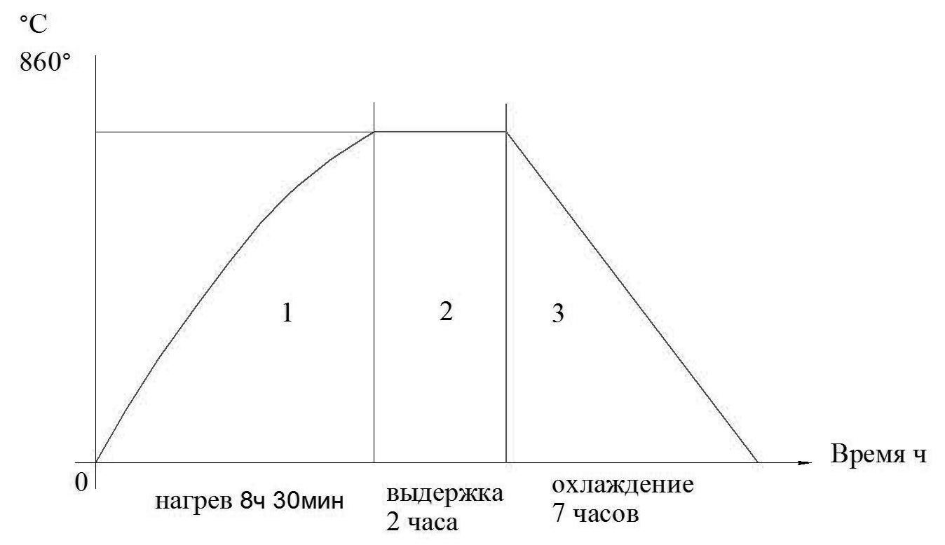
Picture 3.1 – Graph of the annealing mode of high-speed steel P6M5.
The thermal program is the desired dependence of the temperature of an object on time. The part of the program that has a constant rate of temperature change is called a section. Each site is characterized by two parameters - the final temperature and time. Figure 3.1 shows three sections: 1 - heating, 2 - exposure, 3 - cooling. The controller executes the program sequentially, section by section, until it detects the end of the program section, after which it stops executing the program and goes into standby mode. In standby mode, the thermal program is not executed, the main and additional outputs are open, there is no current in the load. Here you can control the temperature of the object and enter the necessary parameters, and in automatic mode it is impossible to change the set parameters.
When the site is changed, the thermocouple breaks and the furnace overheats, the program controller generates sound signals. The emergency temperature at which the emergency exit is triggered and the regulator goes into standby mode is usually set to 20...50 .C is greater than the maximum temperature of the thermal program, but not more than the maximum permissible temperature for this object. The controller in automatic operation mode, when the mains voltage is lost, stores the current process parameters in memory and after the power supply appears, continues to execute the thermal program from the interrupted place.
4. A critical review of well-known technical solutions for automation of a high-temperature chamber furnace.
The use of automated control systems during heat treatment improves the quality of products and facilitates the work of service personnel. Modern equipment and new methods of automatic control make it possible to reduce the costs of repair and maintenance of equipment, to obtain an economic effect from the rational use of energy resources due to optimal process control. Let's consider two design solutions for the modernization of the control system of electric furnaces, taking into account such technological needs as precise temperature control, the possibility of rapid regime change when processing various types of products.
Temperature control systems in electric furnaces based on OVEN.
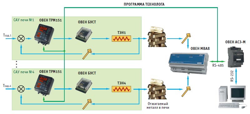
Picture 4.1 – OVEN interface converter.
As a regulating device in the electric furnace control system, a two-channel software PID controllerOVEN TRM151 is used, two channels of which regulate the temperature on the heating elements. The actuating device is theOVEN BOOST triac and thyristor control unit, which ensures the accuracy of automatic power adjustment on the heating elements of the furnace by the phase control method. To expand the inputs and obtain an additional possibility of measuring the temperature in the product itself or in the furnace muffle, the input moduleOVEN MWA8 is used. Data exchange between the regulators and the analog input module is carried out using a computer, anOVEN AC3-M interface converter is used to coordinate the RS-485/RS-232 interfaces.
The developed system allows performing annealing mode of any degree of complexity. The technologist's programs are created on a top-level computer and are entered into each TRM151 device.
For more complex systems with control of three or more heating zones, as well as the operation of fans and other actuators, a system with a control device in the form of a programmable logic controller, for example,OVEN PLC, will be the most acceptable. An example of this type of installation can be the most common type of furnaces in the industry – a chamber electric resistance furnace, or a bell-shaped electric furnace. In these furnaces, depending on the design, there may be three heating zones. For optimal temperature control in them, it is necessary to have three independent control circuits. The system regulates the temperature in each heating zone: in the first, second and third zones using, respectively, the first, second and third control channels. All circuits are subject to the main temperature control circuit in the muffle. The circuits of the subordinate regulation are identical and consist of a temperature controller programmatically implemented in the controller (ARIES PLK154), an executive device (OVEN BOOST and triacs) and a control object (heating elements). The controller of the main control circuit, as well as the controllers of the subordinate circuits, is programmatically implemented in the controller PLK154.
Data from each channel is transmitted first to the controller, and then to the computer, where it is processed and stored using a SCADA system adapted to work with this technological process and the selected controller. In the developed system, in addition to automatic temperature control, it is possible to regulate using manual control resistors. Manual operation is used during setup or emergency.
The main control and controlling elements of the SU chamber furnace are:
A distinctive feature of the project using a PLC is the ability to visualize the temperature control process in the selected electric furnace on a computer.
5. Development of the algorithm of operation and circuit solutions of the automatic control device of a high-temperature chamber furnace.
Heat treatment is the treatment of materials associated with their cooling or heating and aimed at changing the properties of materials. Metals and alloys, as well as non-metallic materials, are subjected to thermal and thermocyclic treatment to improve the crystal structure, for example, to obtain a fine-grained structure of the base material of bimetallic compositions obtained by co-heating, or to increase the adhesive bond strength of bimetal layers. This article discusses an automated technological process of heat treatment of ceramic products in a chamber furnace, the purpose of which is removal of harmful impurities, changing the chemical and physical properties of the material or giving the product the necessary qualities (mechanical strength, chemical resistance, heat resistance, fire resistance, etc.). Metal-ceramic compositions are used, for example, in the aircraft industry, where high accuracy of the technological regime is required in the manufacture of the product.
The technological process of heat treatment of ceramic rods consists of a sequence of steps of heating, cooling or holding. To successfully complete the processing of the product, it is necessary to monitor the current temperature of the heating device (in this case, a chamber furnace) for a long time (5-6 hours), switching the operating modes of the device. To increase the level of product quality control, it is recommended to use a data collection and accounting system to analyze the production cycle of each of the products. For this purpose, a complete automated process control system with all the necessary components is being introduced into the production structure. The heat treatment of the workpiece of the product is carried out according to a certain algorithm. This algorithm consists of a sequence of steps of heating (increasing the temperature in the furnace), cooling (decreasing the temperature) or holding (holding a certain temperature value for a given time). Each of the steps has its corresponding parameters: the heating rate, the temperature at the end of the step (that is, the temperature to which the product needs to be heated or cooled at this stage of the algorithm).
The algorithm of the furnace operation consists in the fact that the processed part is laid out on the under, the door opens, then the under moves inside the furnace. After the end of the heat treatment, the actions are repeated in reverse order, after which the full treatment cycle is completed. The heating is controlled by a software controller. The system uses pulse control – the controller program outputs the width of the controlled pulse, that is, the power with which the furnace should be heated (or cooled).
The PLC, in turn, operates with 2 temperature values to obtain a conditional power value at its output: the current one (obtained from a thermocouple installed inside the furnace) and the desired one (the one that should be in the furnace according to the heat treatment algorithm). In order to obtain the necessary pulse width, it is convenient to use PID regulation. Thus, the PLC performing the control must support the possibility of this type of regulation.
The implemented control system from the point of view of the program architecture can be represented in the form of finite automata. The system can accept a certain number of states, the transition between which occurs due to the processing of events occurring in it by the system.
Initial state - the state in which the PLC is located at startup: at the same time, the initial setup (initialization), loading data from memory, resetting inputs is carried out. Waiting is the state in which the PLC is when it is waiting for commands to switch to other states. Execution – execution of the program code that starts the execution of a specific selected sequence. Sequence editing is the state when editing, deleting, or adding a new sequence to memory for subsequent execution. In the form of a finite state machine, the logic of the "Execution" state is also implemented, where there are 3 more states: heating, cooling and exposure. To implement an automated system for controlling this technological process, a controller of the Russian company "ARIES" is proposed, designed to build automation systems of low and medium complexity.
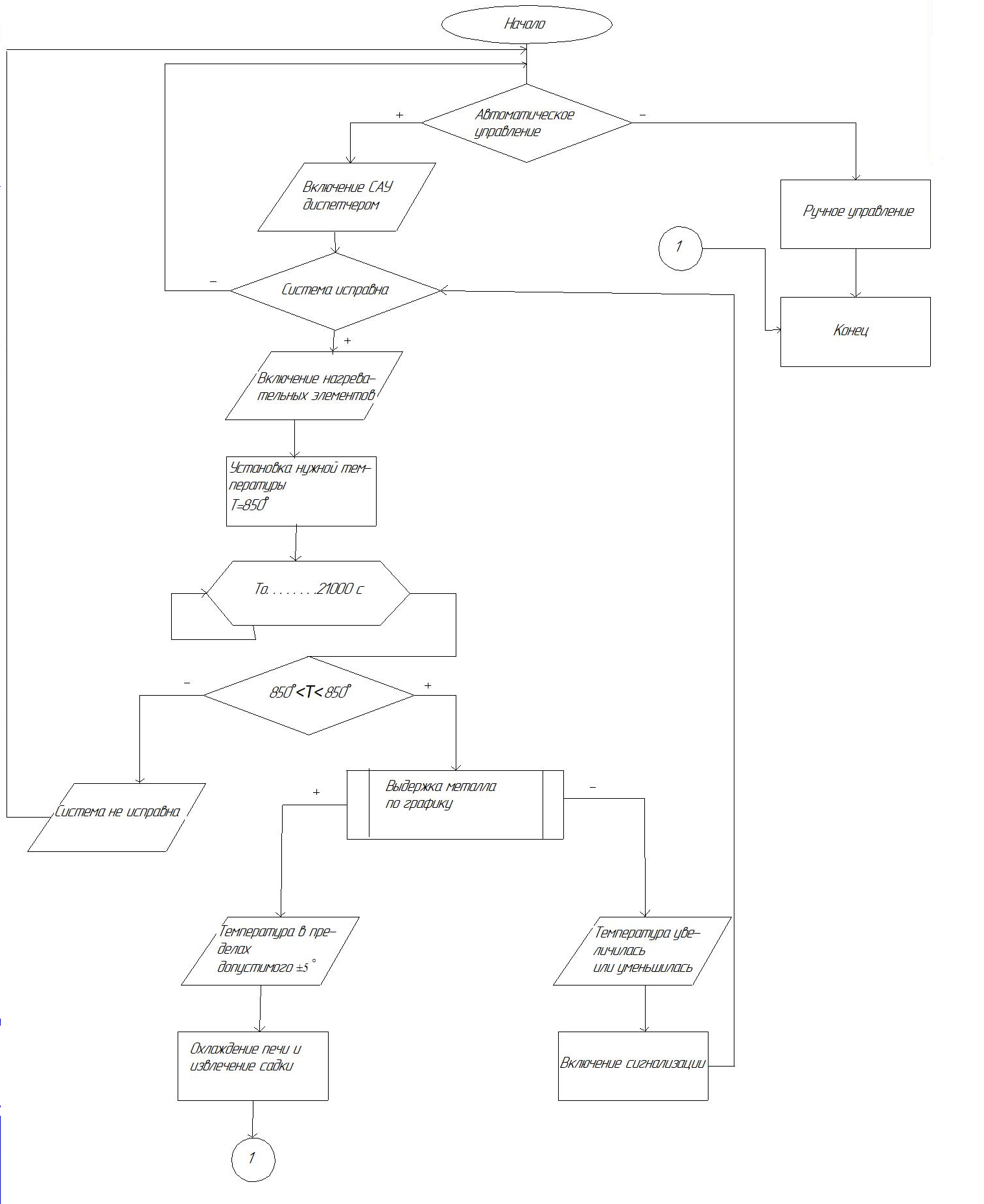
Picture 5.3 – Thermal mode control algorithm
In automatic processes (objects), it is quite often necessary to change or maintain constant any physical quantities called controlled variables, in this case, temperature maintenance.
For this purpose, automatic regulators or control devices (UUS) of varying complexity are used.
The automatic controller and the control unit, based on the measurement of regulated variables and setting influences, forms a control effect on the object of regulation.
Figure 5.4 shows a block diagram of the control of an electric furnace for annealing workpieces with an adjustable value of y(t) - temperature. This system is designed to maintain the required mode, i.e. temperature changes y (t) in the electric furnace according to a given law.
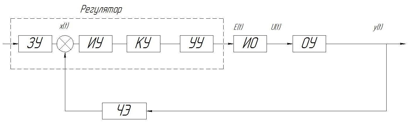
Picture – 5.4 Control block diagram.
The circuit consists of a control object and a control device. The control object (OU) is the main element of the system, that is, an electric furnace, the set operating mode of which must be supported by a control device (software thermostat) with the help of control (regulatory) bodies. A control means a device that provides the control process, i.e. a purposeful action that leads to the desired change in the controlled variable (temperature of heating, exposure, cooling). To reduce the control error, feedback is introduced into the system. The setting device (memory) exerts a control effect of Uz (t) on the input of the system, forming a program for changing the controlled value. The memory sends a signal to the actuator (IM) - transformer, which is directly the corrective link of the system. The control action is adjusted depending on the output value y(t). The sensing element (CE) converts the controlled value into a proportional value and convenient for use in the ACS. As this element, a thermocouple is used, at the output of which a voltage is formed proportional to the temperature in the furnace. This signal is then fed to the measuring device. The comparison device performs the identification of the correspondences of the required and received values. If the value of y (t) deviates from the set value, then the signal is corrected through an amplifying device (USU) and a correction device. The temperature change signal is supplied by a thermocouple to the PLC-154 temperature control device, where a comparison is made in the control device with the temperature set by the operator, and a command is issued to turn on or off the load.
Conclusions
The technological process of firing parts in a high-temperature chamber furnace as an automation object was analyzed and the requirements for the control system were formed. Its trouble-free operation requires constant monitoring of parameters such as the temperature of the chamber space. The result was • The choice of the optimal universal, easy-to-use modern control device, in accordance with the output signals of temperature sensors, as well as the choice of auxiliary controls, is justified. The algorithm allows for automatic continuous temperature control inside the furnace, and automatically turn off the electricity in case of an emergency temperature rise.
When writing this abstract, the master's work has not yet been completed. Final completion: May 2023. Full text of the work and materials on the topic can be obtained from the author or his supervisor after the specified date.
List of sources
- Campos I.B., Aguirrezabala N.N.,Valdes L.D. Ezenarro B.E., Arantzamendi H.G. Energy efficiency and line productivity improvements for a continuous heat treatment process. – Industrial Summer Study on Industrial Efficiency: Leading the Low-Carbon Transition, Kalkscheune, Berlin, Germany, 2018. P. 431 – 441.
- Гринчук П.С., Торопов В.В. Ознобишин А.Н., Кияшко М.В., Дмитриев С.И., Замедленное остывания металла в современных энергоэффективных печах // Известия национальной академии наук Беларуси. Серия физико-технических наук. –2013. – №1. – С. 82 – 88.
- Гурьев А. М., Иванов С. Г., Гурьев М. А., Бердыченко А. А., Черных Е. В. Влияние режимов термической обработки на структуру и физико-механические свойства быстрорежущей стали // Фундаментальные проблемы современного материаловедения.– 2018.– №1.– С. 103– 108.
- Ишимбаев А.В., Матюхин В.И. Совершенствование конструкции камерной нагревательной печи с изменяющейся рабочей температурой // Теплотехника и информатика в образовании, науке и производстве: сб. науч. тр. Екатеринбург, 2021. – С. 62 –64.
- Кабишов С.М., Ратников П.Э., Трусова И.А., Менделеев Д.В. Оценка влияния конструкции футеровки на величину тепловых потерь при работе камерной печи // Литье и Металлургия. –2015. – №4(81). – С. 108 – 115.
- Панферов В.И., Панферов С.В. К решению задачи об управляемости нагрева металла в промышленных печах // Вестник Южно-Уральского государственного университета. Серия: Металлургия. –2019. – №2. – С. 79 – 85.
- Панферов В.И., Панферов С.В. К решению задачи об управляемости нагрева металла в промышленных печах // Вестник Южно-Уральского государственного университета. Серия: Металлургия. –2019. – №2. – С. 79 – 85.
- Погребисский М.Я., Усачев Р.А. Выбор схемы размещения нагревателей в камерной печи сопротивления на температуру 1200-1250°С // Электромеханика, электротехнологии, электротехнические материалы и компоненты. – Алушта, 2016. – С. 236 –237.
- Скоробогатова И. В. Синтез системы автоматического управления энергосберегающими режимами камерной печи // Сборник научных работ Донецкого института железного транспорта. –2014. – №37. – С. 53 – 59.
- Н. В. Пасечник, Энциклопедия. Т.4-5 Машины и агрегаты металлургического производства / Н. В. Пасечник В. М. Синицкий, В. Г. Дрозд и др. — Под общ. ред. В. М. Синицкого, Н. В. Пасечника. — М.: Машиностроение, 2000. — 912 с.
- Слащев М.Н. Автоматизированная система управления тепловым режимом камерной печи для термообработки металлопроката // Конкурс научно-исследовательских работ студентов Волгоградского государственного технического университета. –2020. С. 41.