
Summary on the topic of the final work
Content
- Introduction
- 1. Relevance of the topic
- 2. Purpose and objectives of the study, planned results
- 3. Research and Development Overview
- 3.1 The technological process of production of the heat carrier of the heat and power plant of the metallurgical plant as an object of automation
- 3.2 Overview of well-known technical solutions for automation of boiler installations
- 3.3 Block diagram of the developed automation system
- Conclusions
- References
Introduction
A modern boiler plant is a complex structure that includes various equipment connected into a single whole by a common technological scheme, the main element of which is the boiler unit. It is the boiler unit that is designed to produce the required amount of the final product of steam or hot water with the quality indicators set by the consumer.
The energy source for boiler installations for various purposes are natural and artificial fuels in solid, liquid and gaseous states, the heat of the outgoing gases of technological installations, the heat of exothermic transformations released in individual technological processes, etc. In this paper, a steam drum boiler equipped with a gas furnace is considered. The efficiency of the furnaces of all types is primarily determined by the efficiency of the gorenje process. Gorenje process efficiency, in turn, is ensured by maintaining the required level of the ratio "fuel-air". Thus, that primary role is predetermined, which is played in the control system of the furnace device of the system of automatic regulation of fuel supply and blast air pressure.
One of the significant problems of the Donetsk Metallurgical Plant's energy sector is the insufficiently efficient use of associated fuel (blast furnace gas) obtained at production of pig iron in blast furnaces. The uneven course of metallurgical processes is due to the instability of the production and consumption of blast furnace gas, which leads to significant pressure fluctuations in gas pipelines, to an increase in direct losses through discharge plugs, deterioration of the operating modes of the main metallurgical units: heating wells, furnaces of rolling mills, etc.
The main consumer of blast furnace fuel are CHP-PVS boilers, in most cases they are not able to ensure its full consumption and pressure stabilization in the main gas pipelines. One of the main reasons is the insufficient level of automation of means for controlling the fuel supply to the boiler furnace. To solve this problem, it is necessary to provide timely information about the caloric content and pressure of the blast furnace gas before feeding it into the furnace. To maintain the required level of the fuel-air ratio, it is necessary to measure the amount of oxygen in the exhaust gases, for which a stationary gas analyzer is used. It should be added to this that the efficiency of the boiler unit as a whole is determined by the quality indicators of the final product, which in this case is steam.
The heat transfer of the furnace is the control action for the steam generation system. Therefore, in order to maintain the steam pressure at a given level, it is necessary to adjust the settings of the fuel supply regulator accordingly. The need for such a connection is indicated in many literary sources. However, due to the peculiarities of the manufacture and installation of the boiler unit, there is practically no such connection anywhere. Each of these control systems functions independently, reacting only to external and internal factors. The connection between them is carried out only through the heating process, and one–way - from the furnace to the drum. It is clear that this leads to a significant decrease in the efficiency of the main technological parameters of the steam generating system [1].
With that said, the purpose of this work is to ensure the efficiency, reliability and safety of the steam boiler unit by automatic regulation the main technological parameters of the gas furnace device will lead to an increase in the actual performance of the CHP while reducing the cost of steam, electricity and heat, since the automated system can function continuously in real time ensuring the efficiency of the gorenje process and taking into account the operating modes and dynamic properties of the steam generating system in the form of appropriate corrective links.
1. Relevance of the topic
An increase in the efficiency of the use of secondary energy resources can be achieved by improving the main and auxiliary equipment of a thermal power plant (CHP-PVS), their thermal and start-up circuits, automated process control systems (APCS) and operation technology, as well as the introduction of new replacement equipment. The technical and economic indicators of the CHP-PVS depend on the characteristics of the main equipment and the type of fuel burned, especially when burning various coals, as well as on the technological scheme of heat release. At the same time, the efficiency of boilers and heat-generating steam turbine units is of the utmost importance. Therefore, developments aimed at improving the efficiency of the technology of using secondary energy resources such as (blast furnace gas) obtained during the production of pig iron in blast furnaces are relevant. This is especially important for the reconstruction and technical re-equipment of the automated control system of the CHP-PVS, whose equipment has exhausted its resource.
The main elements of the boiler room include:
A boiler is a heat exchange device in which heat from hot fuel combustion products is transferred to water. As a result of this in steam boilers, water turns into steam, and in hot water boilers it is heated to the required temperature. The furnace device is used for combustion fuel and the conversion of its chemical energy into the heat of heated gases. Feeding devices (pumps, injectors) are designed to supply water to the boiler. Even the simplest boiler plant cannot work without these elements.
Auxiliary elements of the boiler room include:
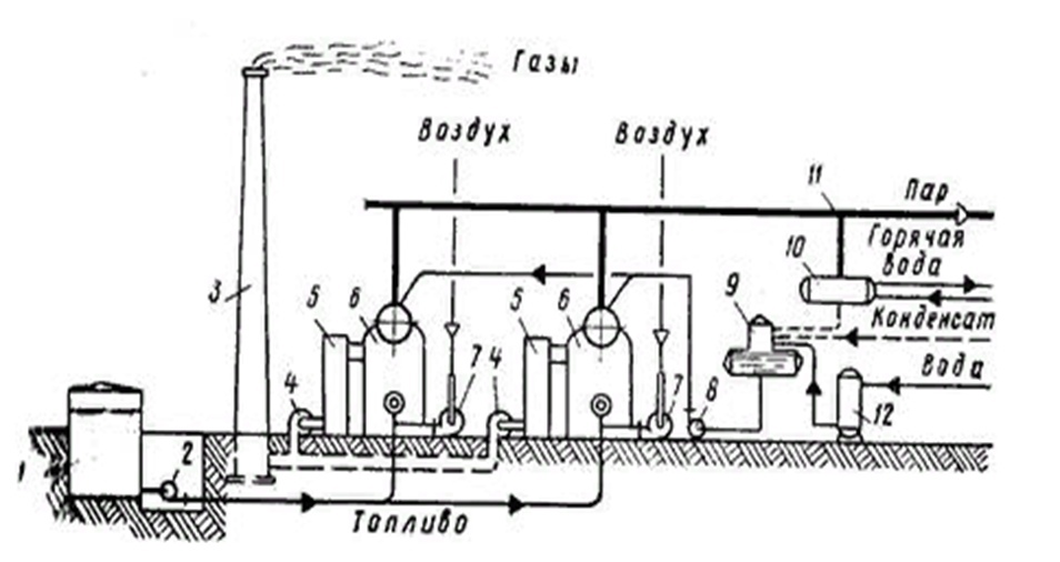
Figure 1 – Diagram of the boiler plant: 1 – fuel storage; 2 - fuel pump; 3 – chimney; 4 – smoke pumps; 5 – water economizers; 6 – steam boilers; 7 – blow fans; 8 – feed pumps; 9 – deaerator; 10 – water heater; 11 – steam line; 12 – water treatment plant.
2. Purpose and objectives of the study, planned results
Heat production is always a very important problem of modern life, and modernization and improvement of this process are always relevant. At the moment, boiler installations are in urgent need of modernization, since they are practically not automated and most processes are controlled by a person manually, making mistakes. As a rule, in many boiler houses, most boiler parameter control systems are still operating in manual mode, which leads to serious environmental pollution and the inefficient use of fuel in the modes of excess or lack of gorenje air.
The purpose of this work is to analyze the technological parameters of the gas furnace device for its subsequent automation to ensure timely informing about the caloric content and pressure of the blast furnace gas before feeding it into the furnace. A full-fledged solution to the problem of efficient combustion of the oxodomain mixture on boilers by the creation of all-mode controllers became possible only with the mass distribution of highly reliable programmable logic controllers.
The main objectives of the study:
- analysis of the boiler plant as an automation object;
- analysis of existing developments on automation of heat carrier production of the heat power plant;
- development of a mathematical model for the production of a heat carrier of a heat and power plant of a metallurgical plant;
- development of circuit solutions. Structural, functional diagram of the automation device, algorithm of operation;
- practical implementation of the automated control system of the boiler plant. Development mnemonic circuits for controlling the production of heat carrier of the heat and power plant of the metallurgical plant;
- development of measures for safe and trouble-free operation of the developed device.
The object of the study: boiler plant.
Subject of research: automatic control system for the production of heat carrier of the heat and power plant of the metallurgical plant.
3. Research and Development Overview
3.1 The technological process of production of the heat carrier of the heat and power plant of the metallurgical plant as an object of automation
The object of automation is a boiler of the BG 3-75-39FB type - single-drum, U-shaped layout, vertically-water-tube, with natural circulation. The boiler consists of: a furnace chamber and burner devices, a superheater, a water economizer, a tubular air heater. Technological scheme the device and operation of the boiler house based on the boiler type PC 3-75-39FB is shown in Figure 2.
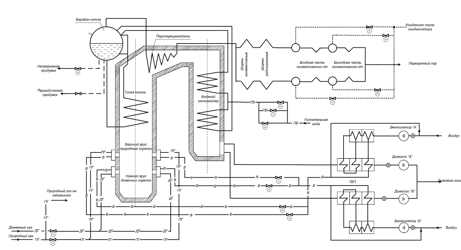
Figure 2 – Flow diagram of the device and operation of the boiler type BK3-75-39FB
The volume of the furnace chamber is 454 m3, the walls of the furnace are completely shielded by pipes with a diameter (60x3) mm, made of steel St. 20. The heating screen surfaces are broken for 12 independent circulation circuits according to the number of mounting blocks.
Number of pipes:
Natural gas is used as fuel, as well as blast furnace gas - an artificial type of fuel obtained as a by-product in the production of cast iron. Steam acts as a heat carrier. The main workshops, closely related in technology, are boiler-turbine and chemical water treatment. To get steam a three-stage evaporation scheme is used in the boiler of normal quality. The first stage of evaporation (clean compartment) and the second stage (salt compartments) are located directly in the boiler drum. Remote cyclones are the third stage of evaporation.
The first stage of evaporation includes the central part of the boiler drum with blocks of front, rear and front blocks of side screens. In the second stage are allocated the end parts of the drum, separated from the central part by partitions. The circulation circuit of the second stage includes the middle blocks of side screens. To the third stage external cyclones with a diameter of (377x18) mm are included in the evaporation, and the rear blocks of side screens are included in the circulation circuit of the third stage. The power supply of remote cyclones is carried out non-heated pipes with a diameter of (83x3.5) mm from the salt compartments of the drum. Separation devices of the first stage of evaporation consist of a recessed perforated steam intake the ceiling. [4]
In the second stage of evaporation, two inside drum cyclones and steam inlet boxes are installed (at each end of the drum), changing the direction steam movements. In the third stage of evaporation, the separation elements are: the snail of the remote cyclone itself and the perforated steam intake ceiling.
Feed water from the water economizer enters the boiler drum through 10 pipes with a diameter of (60x3) mm and is directed through the transfer case to the flushing (perforated) shields, flows through them and merges into the water volume of the drum. The average working water level in the Clean Compartment is 50 mm below the drum axis. The boiler water enters the salt compartments from the clean compartment through pipes mounted in the lower parts of the partitions. The steam-water mixture from the output collectors of the third stage of evaporation enters the snails of the remote cyclones, and the separated steam from the remote cyclones through pipes with a diameter of (83x3.5) mm enters the corresponding salt compartment of the drum.
The steam-water mixture from the screen circuits of the second stage enters into the drum cyclones installed in salt compartments. The water separated in the cyclones is drained into the water volume of the salt compartment, and the steam passes through the louver separators located above the cyclones, mixes with the steam of the third stage and is sent through the boxes to the steam space of the clean compartment of the drum. The steam-water mixture from the screen system of the first stage enters under perforated sheets immersed in water 50 mm below the lowest water level in the drum. The steam passes through them, mixes with the steam coming from the soy compartments, and, after passing the louver bag and the steam intake hole ceiling, it is sent to the superheater. The circulation scheme of the boiler provides for deep partitioning of the screens, which increases the reliability of the circulation of the steam-water mixture in the boiler screens.
A convective superheater is installed on the boiler, located behind a four-row festoon in a transitional horizontal flue. The superheater is made in two stages, the heating surface area of each stage is 220 m2. The scheme of switching on the superheater relative to the direction of movement of the exhaust gases is mixed. Steam from the drum passes through 72 pipes with a diameter of (38x3) mm through the first stage of the superheater and enters the output collector with a diameter of (273x25) mm. From the output collector of the first stage, a pair of 10 pipes with a diameter of (83x5) mm (cross flow through 5 pipes on the left and right sides of the collector) is diverted into two collectors with a diameter of (325x25) mm. Further, steam passes through 36 pipes with a diameter of (38x3) mm through the second stage of the superheater and enters the intermediate collector with a diameter of (273x25) mm. From the side parts of the intermediate collector, steam enters the middle part and then passes through 72 coils with a diameter of (38x3) mm through the middle part of the second stage of the superheater, and then enters the output collector of the superheater with a diameter of (273x25) mm and further into the steam line.
The water economizer and the air heater are located in the descending flue into the dissection. Boiling type water economizer, coil type, two-stage, the heating surface of the first stage is 700 m2, the second stage is 240 m2. The first stage of the water economizer consists of 41 coils with a diameter (32x3) mm made of 20 steel, the second stage of the water economizer consists of 48 coils of the same diameter and material. After the power supply unit, water is supplied to the inlet collector of the first stage of the water economizer by a pipe with a diameter (108x10) mm. The estimated feed water temperature is 150 °C. After passing the coils of the first stage, water from the outlet collector enters the inlet collector of the second stage by 6 pipes with a diameter (66x3) mm in a cross flow. After passing the second stage, feed water is discharged into the boiler drum through two outlet collectors located on the side walls with 10 pipes (60x3) mm in diameter (5 pipes from each collector). All five collectors of the water economizer are made of pipes with a diameter (219x16) mm. The boiler air heater is tubular, single-flow through gases and four-way through air, consists of steel pipes with a diameter of (40x1.5) mm, the heating surface of the first (cold) stage is 2600 m2, the second (hot) stage is 1600 m2
The draft installation of the boiler consists of one blast fan type VD-18 and one smoke pump type D 20x2. Air with a temperature from 30 ° C to 50 ° C is sucked by a fan from the boiler room and, passing through the air heater, is supplied to the gas burners through air ducts. The flue gases are sucked out by the smoke pump and discharged into the chimney. The resistance of the boiler unit for flue gases, depending on the type of fuel, ranges from 116 to 148 mm of water. art. Air resistance from 73 to 87 mm of water. art.
The boiler is designed to work with balanced thrust (the air supply for gorenje is carried out by a blow fan, and the removal of combustion products - by a smoke pump). Regulation of the supply and pressure of the smoke pump and fan is carried out by guiding devices installed on the suction side.
The main parameter responsible for controlling the production of coolant in the heat and power plant of the metallurgical plant, which can be automated, is the regulation of fuel supply to the boiler furnace. In the boiler furnace, blast furnace and natural gas are burned together or separately. To burn these fuels, the boiler furnace is equipped with two flat flare burners, the burner consists of two gas-air nozzles inclined at an angle of 60 ° to each other. The upper nozzle consists of coaxially arranged rectangular boxes for blast furnace gas and air. Blast furnace gas is supplied through a central box, the internal dimensions of which are equal to (0.39x0.74) m. Hot air for gorenje enters through the outer box of the upper gas-air nozzle. The dimensions of the latter are (0.6x0.9) m. The lower gas-air nozzle is a natural gas burner and consists of an air box measuring (0.5x0.5) m, inside of which ten gas-distributing pipes with a diameter of (42x3) mm are arranged in two rows vertically. Between the upper and lower gas-air nozzles, a pipe for the ignition device and a pipe for the main torch sensor are installed. The technical characteristics of the combined flat-pack burner are given below:
Burner performance by:
Burner resistance by:
Maximum air resistance:
The principle of operation of a flat-pack burner is based on the use of the effect of collision of two air jets directed at an angle to each other. A "triangle" is formed between these flows, into which incandescent combustion products are ejected from the sides, which warm up and ignite the fuel. The collision of two streams leads to the formation of a flat jet with a high degree of turbulence and a highly developed surface, which contributes to the intensive combustion of fuel in the volume of the furnace. When working on blast furnace gas, the gas-air pulse of the upper nozzle is more powerful than the pulse of the lower nozzle. Therefore, the torch shifts to the hearth of the furnace. The heat perception of the lower part of the furnace increases, which leads to a decrease in the temperature of gases at the outlet of the furnace. This allows you to increase the performance of the boiler on blast furnace gas.
When the boiler is running on high-calorie natural gas, the gas-air pulse of the lower nozzle is higher than the upper one. The torch shifts upwards, the temperature of the gases at the outlet of the furnace rises and the temperature of the superheated steam increases. When working on a mixture of fuels, the torch in the furnace occupies an intermediate position. Thus, self-regulation of the temperature of superheated steam is provided. Characteristics of burned fuels. Blast furnace gas is an artificial type of fuel obtained as a by-product in the production of cast iron. Average composition of blast furnace gas:
- carbon dioxide CO2 - 16.2 %;
- methane CH, - 0.2 %;
- oxygen O2, - 0.1 %;
- hydrogen H2 - 4,8 %;
- carbon monoxide CO - 22.8 %;
- nitrogen N2 - 56.0 %;
- heat of combustion Q - 772 kcal/m3;
- density p - 1,298 kt/m
The content of natural gas is determined by the content of methane CH4 in it. Composition of natural gas:
- CH4, - 94,565 %;
- Cm Hn, - 2,34 %;
- CO2 - 0,019 %;
- N2 - 3,076 %;
- the lowest heat of combustion is 7918 kcal/m3;
- the density of p is 0.70 kg/m3.
Thus, the proposed automation of the control system consists in the modernization of the existing control system for the production of coolant through the use of modern automation tools, which in turn will replace outdated equipment. This system of automatic control of coolant production based on a boiler of type BK3-75-39FB, taking into account the specifics of management, will ensure a reduction in natural gas consumption due to mixed modes of operation on two fuels, in ideal conditions only blast furnace gas will be used, which will increase the productivity of the unit, while increasing the efficiency in using natural gas.
3.2 Overview of well-known technical solutions for automation of boiler installations
As an existing automation system, the boiler control system BKZ-75-39GMA is made on the basis of a programmable controller C200HG from OMRON. The steam boiler is an object of increased danger from the point of view of the safety of the operation of production equipment. The operation of the boiler is characterized by information coming from analog and discrete sensors of the state of thermal parameters, position sensors and sensors of the status (on/off) of electric motors. Operational control of the boiler is carried out from the NT620C industrial terminal. The NT620C industrial terminal is used as a control module. The NT620C terminal has extensive capabilities.
The use of such a terminal will allow:
- display the status of the equipment and control system;
- enter the necessary information;
- display the progress of the technological process in the form of mnemonic diagrams;
- perform manual control of equipment and control circuits;
- abandon a large number of warning lights and control buttons.
The basis for the construction of a unified control system is based on the principle of configuring systems from standard modules and blocks that allow solving all the variety of tasks of control and management of technological processes. All modules are interconnected by a high-speed network and can make up any configuration.
- exchanges commands and data with the control module;
- switches on and off the digital outputs;
- the ability to continuously monitor the reliability of all or a certain class of input information with alarm and fault registration of individual sensors or communication channels;
- the possibility of restructuring algorithms when a malfunction is detected;
- the ability to control the execution of commands in fact and in time;
- self-diagnosis of technical means with signaling and registration of failures at the level of a typical replacement element;
- the possibility of authorized monitoring of the status of any sensor or algorithm;
- simplification of the procedure for making operational and non-operational changes with authorized access to such changes with simultaneous automatic registration of the fact of access and the changes made;
- possibility of fixing the time of occurrence of all recorded events;
- automatic preparation of accounting documentation;
- simplification of the protection testing procedure;
- higher maintainability of technical means;
- a significant reduction in the overall dimensions of the technical means implementing the subsystem, while expanding the functions performed;
- the possibility of full redundancy of technical means with minimal complication of the system.
- Теоретические основы разработки и моделирования систем автоматизации: Учебное пособие / А.М. Афонин, Ю.Н. Царегородцев, А.М. Петрова и др. - М.: Форум: НИЦ ИНФРА-М, 2014. - 192 с.
- Глинков, Г.М. АСУ ТП в черной металлургии: учебник для вузов. / Г.М. Глинков, В.А. Маковский – 2-е изд., перераб. и доп. – М.: «Металлургия», 1999. – 310 с.
- Лысенко, В. Г. Топливо. Рациональное сжигание, управление и технологическое использование: Справочное издание. В 3 книгах / В. Г. Лысенко, Я. М. Щелоков, М. Г.Ладыгичев. – Теплотехник, 2004. – 608 с.
- Гусев Ю. М. Основы проектирования котельных установок / Ю. М. Гусев. – [изд. 2-е, перераб. и доп.] – М.: Стройиздат, 1973. – 248 с.
- Справочник эксплуатационника газовых котельных / [под ред. Е. Б. Столпнера]. – Л.: Недра, 1976. – 608 с.
- Липов Ю. М. Котельные установки и парогенераторы / Ю. М. Липов, Ю. М. Третьяков. – Москва-Ижевск: НИЦ «Регулярная и хаотическая динамика», 2003. – 592 с.
- Официальный сайт Донецкого металлургического завода [Электронный ресурс]: Режим доступ: http://dmz.donetsksteel.com/ru/company
- Официальный сайт компании ОВЕН, ПЛК73 контроллер [Электронный ресурс]: Режим доступ: https://owen.ru/product/plk73
During operation, the module performs the following tasks:
All modules have a well-developed self-diagnosis system. The serviceability of signal transmission is checked (checking for the presence of “1” in the presence of an input signal, checking for the presence of “0” - in the absence of a signal), checking for the absence of influence of inputs on each other. The modules have indicators of proper operation. The green LED informs about the correct functioning of the module. In case of a malfunction, the red LED lights up and information about the nature of the malfunction becomes available to the control module
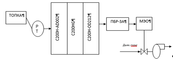
In this case, automation of the discharge control process in the boiler furnace is performed using the Metran – 45 DIV sensor, the Omron C200NG controller, the contactless reversible PBR – 3A starter, the electric single-turn MEO actuator – 630/25 –0,25–87– R and the smoke pump DN-18. The technical characteristics of each of the ASR elements and the functions performed by them are shown below in Figure 3.
Pressure – discharge sensor "Metran – 45 DIV" with a unified current signal of 4-20 mA, with a limit of permissible basic error = 0.5%. The upper limit of measurements is +3.15 kPa. The lower limit of measurements is +0.03 kPa. The temperature range of the measured medium is -40 - +80 ?C. The degree of protection against dust and water is IP65. Explosion protection Ex. Contactless reversible starter PBR – 3A. Manufacturing plant Chelyabinsk, "Plant of electronics and mechanics". The mechanism is single-turn electric, the rated torque on the output shaft is 630 Nm, the full stroke of the output shaft is 25 s, the full stroke of the output shaft is 0.25 turns, a current feedback sensor with a signal of 4-20 mA. Set with power supply BP – 10. Smoke pump DN-18, capacity 143000 cubic meters / h, head 236 mm of water. art., 730 rpm, power 250 kW.
Thus, this automation system is based on the programmable controller C200HG of the company "OMRON", but it has certain disadvantages. The principle of configuring the system consists of using standard modules and expansion units from the company Sysmac. In case of failure (malfunction) of the units included in the unified control system, certain difficulties arise with the replacement of equipment, since the basis for building a unified control system is the principle of configuring systems from standard modules and blocks. This leads to the fact that universality and interchangeability becomes impossible with this technological solution. For any enterprise, downtime is associated with financial losses, violation of deadlines for the delivery of the finished product, loss of the company's image. Unscheduled shutdowns are the lost profits of the plant.
An alternative method of upgrading an automatic control system is the interchangeability and versatility of using programmable controllers. For the basic automation equipment, we will take a widely used installation in modern boiler rooms, namely a PLC from the ARIES company.
3.3 Block diagram of the developed automation system
A programmable logic controller PLK73 from the ARIES company was adopted for the automatic control system of the heat carrier production of the heat and power plant of the metallurgical plant, which, interacting with sensors, it receives information from the control object, processes it in accordance with the embedded algorithm and issues control actions to the actuators. Application microprocessor-based means for implementing a subsystem of technological protections and protective locks provides the following advantages compared to traditional means:
Interaction with sensors and actuators is determined by appropriate exchange protocols that take into account the features of the functioning of the system as a whole and the requirements of software, hardware and circuit compatibility with other devices and systems. The structural diagram shows all the main functional parts of the system (elements, devices and functional groups) and the main relationships between them. The graphical construction of the diagram in Figure 4 provides the best idea of the sequence of interaction of functional parts in the system. The arrows on the relationship lines indicate the direction of the processes occurring in the device.

Figure 4 – Block diagram of coolant production control: 1 - blast furnace gas flow rate D1; 2 - blast furnace gas pressure D2; 3 - natural gas flow rate D3; 4 - power supply BP1; 5 - BRU manual control unit; 6 - contactless reversible PBR starters; 7 - executive electric single-turn MEO mechanism; 8 - logo power BP2 power supply unit; 9 - UP position indicator; 10 - industrial network standard RS 485; 11 - personal computer PC; 12 - control room DP.
Conclusions
As a result of the graduation project, the technological process of production of the heat carrier of the heat and power plant of the metallurgical plant was analyzed. Based on the analysis , the following was compiled block diagram of heat carrier production management.
On the basis of the conducted research, it is possible to proceed to the development of schematic diagrams, and software, automatic control systems for the production of heat carrier of the heat and power plant of the metallurgical plant.
When writing this abstract, the master's work has not yet been completed. Final completion: December 2023. Full text of the work and materials on the topic can be obtained from the author or his supervisor after the specified date.