
Abstract
Contents
- Introduction
- 1: Relevance of the topic
- 2. Purpose and objectives of the study, planned results
- 3. Research and development review
- 3.1 Process analysis of the ventilation of a dead-end mine as an automation object
- 3.2 Critical review of existing technical solutions for mine ventilation automation
- 3.3 Rationale for the direction of research and development
- 4. Algorithmisation and development of circuitry solutions for the automation of the technological process of ventilation of a dead-end mine working
- Conclusions
- List of sources
Introduction
One of the most important measures for creating and maintaining normal conditions that provide the necessary prerequisites for the satisfactory well-being of miners and their life-supporting activities in mines is good ventilation, i.e. providing workplaces with the necessary amount of air
When carrying out preparatory mine workings in gas mines with roadheaders or by drilling and blasting method methane may be released in excess of permissible norms, which is not safe for the workers, it reduces the productivity of mechanisation equipment, there is a possibility of gassing, which may lead to an emergency situation. The mine ventilation process is an essential element of the mine's technological system, aimed at maintaining a normal mine atmosphere, i.e. providing the necessary inflow of fresh air, and ensuring the permissible methane concentration in the mine atmosphere. The process units that perform these functions are local ventilation fans.
Thus, based on the need to maintain the necessary air supply in the mine, the development of an automation system for the ventilation of a dead-end mine is an urgent task.
1. Relevance of the topic
The problem of ensuring effective ventilation of coal mines is a major limiting factor for coal production at any particular mine. The maximum rate of coal production depends, on the one hand, on the capacity of the ventilation system to dilute harmful substances to acceptable concentrations, and, on the other hand, on the efficiency of degassing methane emission sources.
Ventilation is the main way of diluting and dispersing dangerous gases in underground mines. Air velocities and quantities are maintained at optimum levels to dilute gases, remove dust and control thermal conditions. The more fresh air is supplied to the face, the more of the emitted gas can be diluted[1].
Master's thesis is devoted to the actual scientific task of improving the system of automated control of ventilation of dead-end mine workings. The developed system will improve the reliability and safety of ventilation process of blind drifts, will allow to react timely to arising problems in the process of ventilation and automatically regulate the supply of local ventilation fan.
2. Purpose and objectives of the study, planned results
The aim of the study is to increase the efficiency of the technological process of ventilation of the blind drift by developing the system of automation of the process of ventilation of the blind drift.
The automation object is a local ventilation fan
The existing equipment for automated ventilation of preparatory mine workings does not have means for automatic, operational regulation of the fan performance. The proposed device allows to react automatically to changes in the state of the mine atmosphere and to change the speed of the fan, thereby regulating the amount of air supplied to the mine workings.
In order to achieve this objective, the following tasks need to be carried out:
- Conduct an analytical review of the issues involved in automated mine ventilation;
- Justify the parameters and structure of technical solutions to increase the efficiency of mine ventilation;
- Develop an algorithm, structural and functional diagram of the mine ventilation automation;
- Develop requirements for the operation of mine ventilation automation;
- To carry out a feasibility study on the efficiency of production and the use of mine automation.
3. Research and development review
3.1 Process analysis of the ventilation of a dead-end mine as an automation object
The main task of mine preparation ventilation is to supply the bottom-hole with enough air to effectively ventilate both the bottom-hole part and the entire mine. The amount of air is determined by the requirements of the Mine Safety Regulations, based on the necessity to avoid local and formation methane accumulations, removal of the mine workings within the shortest calculated time to eliminate the toxic products of the The amount of air is specified in accordance with the Mine Safety Regulations.
The main impact on the mine atmosphere is caused by Methane gas emitted from mine workings The main impact on the mine's atmosphere is methane gas emitted from the mine workings, because the concentration of methane in workplaces and methane gas in The concentration of methane in workplaces and outflows is what governs the entire underground of coal mining. Current safety standards for coal mines include The methane content in underground mines is taken with a margin, e.g. 1% in in case of an explosive concentrations of 5%. The reason for this is lack of automatic ventilation control systems in coal mines ventilation systems that allow for a quick impact on the mine's atmosphere. atmosphere.
The ventilation of longwall preparatory workings is usually carried out by blowing using one or more fans installed in parallel, operating on a large-diameter pipeline or on two parallel pipelines, or by cascading several fans at the beginning of a pipeline[2].
The method of ventilation of preparatory mine workings by means of blower LVF is the most widely spread, and at gassed mines it is obligatory and the only one. The technological scheme of the method of forced ventilation of mine drifting by means of the fan LVF is resulted in See figure 1. Where 1 - LVF; 2 - ventilation pipeline.
Figure 1 - Process diagram of the pressurised method of ventilation
Where 1-LVF; 2-Ventilation pipe.
The automation object is the BM-6M fan.
Fan BM-6M is designed for ventilation of dead-end mine workings in mines, including gaseous and dusty ones, with air density up to 1,3 kg/m, at temperature from -20°C to +35°C, dustiness up to 50 mg/m and relative humidity up to 95% (at temperature of +25°C). Aerodynamic characteristics allow to use the fan in excavations 600 m long - with one fan, and up to 1000 m long - with two fans. The explosion protection is ensured by using flameproof electric motors the casings of which correspond to protection IP54. Technical characteristics of the fan BM-6M are given in Table 1.
| Parameter | Value |
|---|---|
| Nominal diameter, mm | 600 |
| Nominal flow rate, m3/min | 340 |
| Nominal total pressure, Pa | 2000 |
| Maximum efficiency, % | 0,76 |
| Drive power, kW | 15 |
| Nominal speed, rpm | 2950 |
| Weight, kg | 730 |
The BM-6M fan uses an asynchronous electric motor with squirrel-cage rotor type VAOM62-2, rated 24 kW, explosion protection level PB-3B, degree of protection IP-54
The design of the BM-6M fan is shown in figure 2
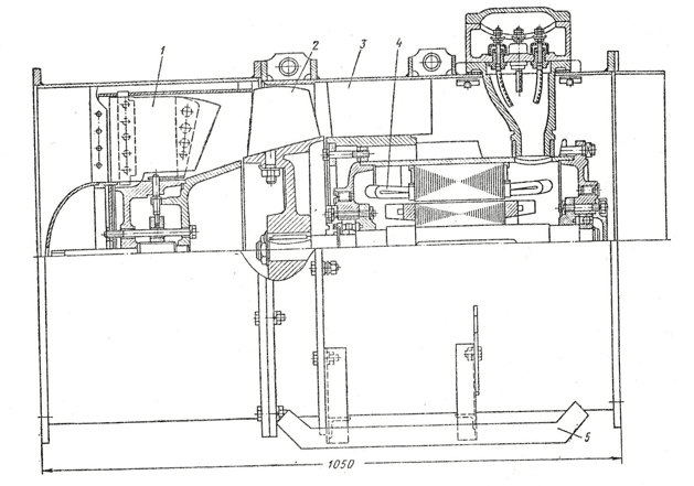
Figure 2 - Design of the BM-6M fan
Fig. 2 shows: 1 - guide apparatus, 2 - impeller, 3 - straightener, 4 - electric motor, 5 - skids
3.2 Critical review of existing technical solutions for mine ventilation automation
The equipment for controlling the ventilation of preparatory mine workings of the type AKTV is designed for automated local and remote control of local ventilation fans, deactivation of power supply in case of deviation from preset mine ventilation modes excavation, supplying information about ventilation of preparation workings to the dispatcher via telemechanics system ventilation of preparation mine workings
The AKTV equipment provides:
- Automatic activation of the standby LVF when the operating LVF fails or is switched off;
- Automatic local and remote (via telemechanics system) control of the LVF;
- Pulse activation of the LVF;
- Automatic pulse restart of the LVF when the power supply voltage fails and is restored on at least one of the LVF;
- Control of the back-up (working) LVF in the event of a planned shutdown of the working (back-up) LVF;
- Monitoring of air flow in the duct (monitored air velocity range 4 to 25 m/s in the duct);
- Discrete air speed setting (setting increment of 1 m/s);
- An adjustable time delay for the activation of the group device from the moment when the pre-set mode of ventilation of the working face is established;
- Automatic shutdown of the group device with adjustable time delay from the moment the preset mode of ventilation is violated;
- Group device tripping without time delay when the LVF starter is switched off;
- Automatic transfer of telemetry equipment and controls to a back-up power supply line when the mains voltage fails and vice versa when the mains voltage is restored;
- The group apparatus can be switched on without time delay after the TPL has been switched on, if the ventilation mode of the excavation has been restored within the adjustable time delay;
- The generation of discrete signals in the tele-mechanics equipment;
- the status (on, off) of the operating and standby LVF;
- the air velocity in the air duct has fallen below the setpoint value;
- on authorising the activation of the group apparatus;
- about the availability of back-up power;
- Short-circuit and open circuit protection of the DSV sensor and UAVV Figure 3 - Block diagram of the AKTV equipment communication line;
- Light indication about:
- the LVF state when it is switched on (off);
- authorising (prohibiting) the activation of a group machine;
- the specified ventilation mode;
- power supply to the working and standby LVF.
The AKTV equipmnent consists of: FAN control unit, a fan control unit; RACS, a duct air velocity control sensor;
A schematic diagram of the AKTV equipment is shown in figure 3
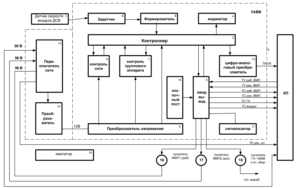
Figure 3 - Block diagram of the AKTV equipment
The DSV sensor continuously outputs an information signal of the current air velocity in the ventilation duct of the preparatory excavation. The signal is transmitted through the two-wire communication line to the shaping unit 3. The level-formed signal from the DSV sensor is sent to the controller 5. The frequency of DSB output signal unambiguously characterizes the monitored average over the section of the pipeline velocity of air coming from VPP. Controller 5 carries out cyclic (2 s) processing of air velocity signal and gives information about air velocity in digital form - on display 4 and in analogue form - at the output of digital-analog converter 12.
When the preparatory mine ventilation mode is normal (Vtek.> Vst.), the controller 5 generates a command to run a 5 - 20 min. time delay (set by the setpoint adjuster) to switch on the group apparatus. After the set time of 5 - 20 minutes has elapsed, the controller 5 issues a command to switch on the group apparatus.
If the preparation workflow is not ventilated (Vtek. The AKTV equipment is supplied with 36 V AC voltage from the starter 1 or 2 LVF connected to the operational and standby substation (PSU). In the event of a mains outage, the AKTV and control equipment are automatically switched over to the back-up mains (mains switch 13). These facilities allow the mine controller to remotely control VMPs and group apparatus by means of the Wind-1M telecontrol and tele-alarm device. As it was mentioned in item 3.1, in order to maintain the necessary amount of air in the mine workings and to prevent gassing of the mine workings, the capacity of local ventilation fans must be adjusted. The reason of it is that during advancing and deepening of mining works, during new excavations and liquidation of old excavations the resistance of mine ventilation system changes. The use of regulated fans also contributes to economical operation of mine ventilation systems. There are several ways to regulate fan performance[3]:3.3 Rationale for the direction of research and development
Fan speed control is the most economical and efficient way of controlling fan performance. Controllable electric drives with various control methods and circuits are used to control the rotation speed of the fan's main shaft.
The fan speed is changed by changing the frequency of the voltage in the stator of the fan motor. Various frequency converter circuits are used to implement this method.[4] When applied to local ventilation fan motors, the most affordable option is to use a frequency converter with a DC link (fig. 4).
The frequency converter power circuit consists of two parts: a rectifier and an inverter. The three-phase alternating current of the mains voltage is first rectified and then inverted back into alternating current at the required frequency and amplitude by the inverter.
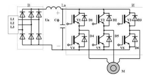
Figure 4 - Frequency converter power diagram
The required output frequency is determined by the switching frequency of the inverter valves and is set by the frequency control channel. The output voltage can be regulated using the pulse width control method of the inverter valves. In this case the input rectifier can be uncontrolled.
In pulse-width modulation, not only is it possible to regulate the average voltage per period, but also to correct the shape of the output voltage. This regulation is called pulse width modulation (PWM).
In this method, the autonomous inverter is based on IGBT transistors, which, if PWM is used, produces a three-phase voltage system at the inverter output which is close to a sinusoidal waveform (Fig. 5).
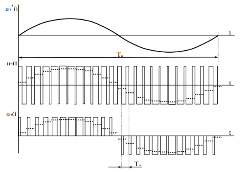
Figure 5 - Bipolar and unipolar pulse width modulation of the autonomous inverter output voltage
The essence of modulation is to adjust the voltage pulse ratio, which varies in a sinusoidal pattern:
γ = γmsin (2πfB+φB)
where γm – modulation depth; fB, φB – frequency and initial phase of the output voltage.
The development of the device for regulating the LVF performance on the basis of the frequency converter will make it possible to continuously monitor the state of the atmosphere of the dead-end excavation and automatically change the rotation speed of the LVF to the required one.
Thus, the aim of the study is to increase the efficiency of the process of ventilation of the blind drift by developing the system of automation of the process of ventilation of the blind drift.
4. Algorithmisation and development of circuitry solutions for the automation of the technological process of ventilation of a dead-end mine working
The operation algorithm of the process control system for the preparation mine ventilation is shown in Figure 6.
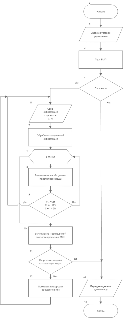
Figure 5 - Block diagram of the process control algorithm for ventilation of a dead-end mine
In the initial phase, when the fan start command is received, the fan is started. If the fan fails to start, the information is transmitted to the mine controller. After successful fan start the information from methane concentration and air speed sensors is collected in the unit 5. The information is further processed in block 6.
After the time delay in block 7, block 8 calculates the optimum air velocity required for good ventilation of the excavation [2]. If the medium parameters are normal, no regulation is required and the sensors are polled according to the new ones. If the medium parameters are not as required, the mine controller is informed and the required fan speed is calculated after a time delay (block 10).
Once the fan speed has been calculated, a check is made to see whether the set fan speed is optimum (unit 11). If the speed is not optimum, the speed is adjusted (unit 12) the cycle is terminated and goes to the start where the sensors are polled again.
Thus, the developed algorithm of operation of the LVF control device makes it possible to continuously monitor the state of the atmosphere of the blind drift and, in case of exceeding the permissible concentration of methane and non-optimal amount of air in the mine working, to automatically regulate the speed of the fan, thereby normalising the parameters of the environment in the mine working
In accordance with the work algorithm, a two-level structure of the automated system for monitoring and control of the technological process of ventilation of the dead end mine workings was developed. It is presented in figure 6.
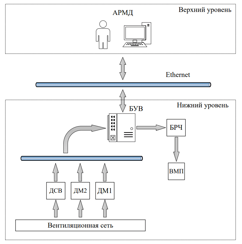
Figure 6 - Schematic diagram of the automated process control system for ventilation of a dead-end mine working
At the top level is the monitoring and supervisory control subsystem, which includes the automated workstation of the dispatcher ARMD. It is an industrial computer connected to the BMS by means of an Ethernet network. It receives information about the process, archives and visualises data and can also be remotely controlled.
On the lower level is the BFU (fan control unit), previously developed, which receives and processes information from the sensors installed in the dead-end excavation and outputs the control signal to the frequency control unit of the VFU.
The block diagram of the fan control unit is shown in fig. 7
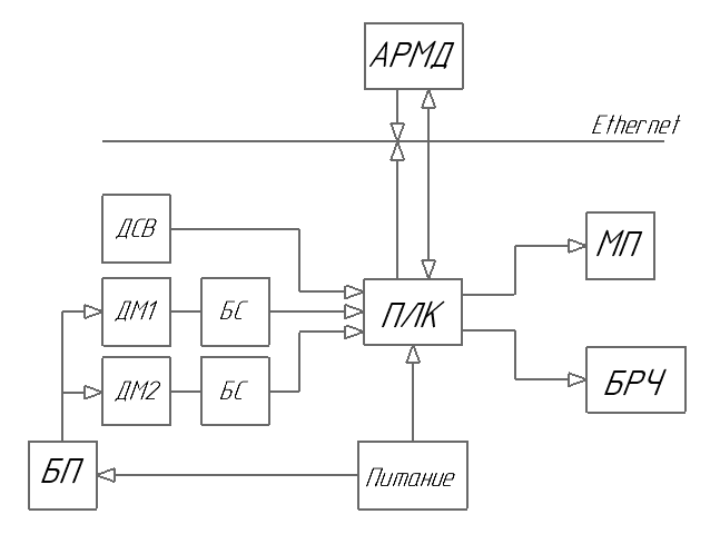
Figure 7 - Schematic diagram of the fan control unit of the process automation system for the ventilation of a dead-end mine
Fig. Figure 7 indicates: ПЛК - programmable logic controller; Д - sensor; БС - matching unit; АС - signalling apparatus; БРЧ - frequency control unit; МП - magnetic starter; АРМД - automated dispatcher workstation.
To visualise the modes of automated technological process of ventilation of the dead-end mine drifting, the SCADA system SCADA TRACE MODE 6 system was used for development and implementation of the UTAS (unified telecommunication system for supervisory control and automated control of The system was used to develop and implement the UTAS safety system (unified telecommunication system for supervisory control and automated control of mining machines and technological complexes)
An example of a visualisation of the process of monitoring and controlling the ventilation process of a dead-end mine is shown in Figure 8.
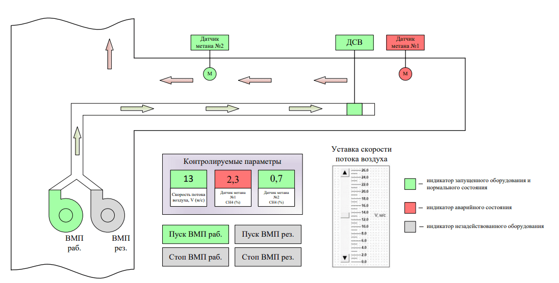
Figure 8 - Process visualisation form for ventilation of a dead-end mine
The mimic diagram of the ventilation process of the mine stalemate is displayed on the PC screen of the Mine Operator's Workstation. Information on the status of local ventilation fans, information on monitored parameters of the mine development is displayed. The dispatcher can also remotely adjust the air velocity in the pipeline and control the fans.
Conclusions
As a result of the master's work, the analysis of the local ventilation fan as an automation object was carried out. The main technological and technical tasks before the development of the automation system were analysed. On the basis of the analysis, review of literary sources the modes of operation, the main features and characteristics of the local ventilation fan were considered.
The algorithm of monitoring and control system operation was developed and based on it, the structural diagram of the control system of the technological process of dead-end mine ventilation was developed. The system has been created that meets all the requirements and objectives. The variant of visualization of process and control of process of ventilation of dead-end mine working is also offered.
At the time of writing this abstract, the master's work is not yet complete. Final completion: June 2023. The full text of the paper and materials on the topic can be obtained from the author or his supervisor after this date.
List of sources
- И.Л.Машковцев. Проветривание горных выработок. - Российский университет дружбы народов, Москва, 1973 г. - 259 стр.
- Г.В. Дуганов, В.Ф. Дробница, И.П. Никитин, А.В. Дребница / Проветривание тупиковых выработок большой длины. Изд-во «Недра», 1968 – 75 с.
- Голинько В.И. Вентиляция шахт и рудников: учеб. пособие / В.И. Голинько, Я.Я. Лебедев, О.А. Муха. – Д.: Национальный горный университет, 2012. – 266 с.
- Учеб. пособ. для студ. высш. учебн. завед. / К.Н. Маренич, Ю.В. Товстик, В.В. Турупалов, С.В. Василец, И.Я. Лизан. – Донецк: ООО «Технопарк ДонГТУ «УНИТЕХ», 2015. – 252 с.
- Александров С.Н., Булгаков Ю.Ф., Яйло В.В. Охрана труда в угольной промышленности: Учебное пособие для студентов горных специальностей высших учебных заведений / Под общей ред. Ю.Ф. Булгакова. – Донецк: РИА ДонНТУ, 2012. - 480с.
- И.Е.Долгий, А.А.Силантьев. Основы горного производства: Учеб. пособие / Санкт-Петербургский государственный горный институт (технический университет), 2003 – 96с.
- Руководство по оборудованию и эксплуатации систем автоматической газовой защиты и централизованного телеконтроля содержания метана АМТ-3 на угольных шахтах / И.Э. Биренберг, А.И. Бобров, М.Г. Гусев и др. – Москва, 1974. – 64с.
- Руководство по ревизии и наладке главных вентиляторных установок шахт / А.С. Гофман, И.С. Меламед, И.Т. Цуцык и др. – М., Недра, 1981. 336 с.
- Методология расчётов гидродинамических параметров шахтных автоматизированных стационарных установок с центробежными нагнетателями / Э.К. Никулин, И.В. Ковалева, К.Н. Маренич – Донецк, 2015. – 134 с
- Правила безопасности в угольных шахтах [Электронный ресурс]: утв. приказом Гос. Комитета горного и техн. надзора ДНР и М-вом угля и энергетики ДНР от 18.04.2016 г. № 36/208: ввод в действие 17.05.2016. Донецк, 2016 – Режим доступа: http://mintek-dnr.ru/zue/pravila_bezopasnosti_na_ugolnykh_shakhtakh.pdf - Дата обращения: 23.05.2021. - Загл. с экрана.