
Content
- Introduction
- 1. Theme urgency
- 2. Goal and tasks of the research
- 3. Description of the technological process of helical rolling in a planetary mill
- 4. The concept of ACS TP for cross-helical rolling in a planetary mill
- 5. Analysis of the robustness of the developed ACS taking into account the main stochastic disturbances
- 6. ACS design
- Conclusion
- References
Introduction
Various designs of rolling mills have been created to meet the requirements for increased productivity, and increasing rationalization of technological performance. Rolling mills are associated with considerable costs, therefore, in order to ensure the efficiency of production, especially in conditions large market demand, it is necessary to achieve a high degree of their use. In this regard, it is advisable develop special deformation methods that ensure proportionality between capital costs and productivity.
The operation of the high-deformation mill is based on the principle of cyclic metal processing, according to which, for each individual cycle, the workpiece moves forward by the same size and timely subjected to compression. High deformation is carried out mainly on pendulum, vibration-forging, planetary-roller, transverse-screw, as well as on universal planetary mills.
Planetary mills in their design and principle of operation differ significantly from conventional rolling mills. There are several types of planetary mills; the most common are the mills designed by Sendzimir and Krupp-Platzer. The main advantage of these mills is the possibility of intensive deformation with a compact composition of equipment. Among the significant advantages of these mills are also the flexibility of technology and the possibility of deformation without a drop in metal temperature. However, these mills have low productivity and complex equipment, which is subject to rapid wear due to the cyclic, inching nature of loading.
1. Theme urgency
Energy saving is one of the main tasks of modernization of metallurgical technologies. Docking a continuous casting machine directly with a rolling mill is possible only with the help of planetary helical stands, the technological parameters of which fully meet the requirements of the process of combining casting and rolling.
The screw planetary mill is a continuously operating unit with a deformation rate exceeding 90%, in which the reduction of the material cross section is carried out by only three rolls in one pass. In continuous operation in a single pass with only three rolls, the same elongation ratio is achieved as, for example, in eight continuous rolling mills with an elongation ratio of up to 15 units. In the planetary stand, the pressed metal does not rotate. Therefore, the planetary helical mill can work continuously in-line with longitudinal finishing mills, where the metal takes shape and quality of the final product. The quality of the tubular billet at the exit from the stand depends on the degree to which the systems for regulating the speed of the rolls and the planetary stand body are implemented in a coordinated manner, so the development of an automatic control system for a multi-motor BRP electric drive is an urgent task.
2. Goal and tasks of the research
The aim of the study is to stabilize the billet reduction process with a large drawing and its small movement around the rolling axis by developing automatic control systems for electric drives of the rolls and the body of the planetary mill for cross-helical rolling of tubular billets.
To achieve this goal, it is necessary to solve the following research tasks:
⁃ to analyze the technological scheme of helical rolling in a planetary mill. Perform an analysis of the electric drive of the BRP planetary mill as an object of automatic control. To substantiate the direction of development of ACS with a twin-engine electric drive of a planetary BRP mill.
⁃ develop a mathematical model of electric drives of a planetary helical rolling mill and check the consistency of the complete mathematical model using mathematical modeling methods.
⁃ perform the synthesis of ACS by electric drives of the planetary helical rolling mill. Analyze the dynamics of the ACS. Check the robustness and performance of the system using mathematical modeling methods.
⁃ develop a functional diagram of the ACS technical means and make a choice of the necessary elements for its technical implementation, on the basis of which to select the required element base. Develop a schematic diagram of the connections of sensors and actuators; develop a control program algorithm and software.
3. Description of the technological process of helical rolling in a planetary mill
The process of cross-helical rolling (PVP) is carried out on two or three rolls rotating in one direction. The axes of the rolls are intersecting or skew straight lines.
On mills for cross-helical rolling, the process of piercing a solid billet is carried out. The original workpieces have a constant cross-section along the length. They are produced by continuous casting and rolling. Ingots have the form of a cylinder or a regular polyhedral prism of a solid or hollow cylinder. Rolling is carried out, as a rule, in a hot state.
In recent years, there has been a trend towards the development of metallurgical mini-mills, which implement energy-saving technologies for the production of steel and rolled products. Energy saving in metallurgy consists in joining the processes of continuous casting and continuous rolling from liquid metal to final rolled products. The faster the metal comes from a liquid state to the final product, the better the economic performance of energy-intensive metallurgical production. In order to combine two continuous technologies, planetary helical rolling stands are used.
Rotary helical rolling stands are generally made with three rolls. The most well-known is the design of the Siemag stands (Fig. 1), where three conical rolls located at a roll angle of 45° to the rolling axis and at an angle of 120° to each other rotate around their axis and, together with the stand, rotate relative to the rolled metal in planetary motion. , forming a cone-shaped deformation zone around the fixed workpiece. Due to the rotation of the axes of the rolls relative to the axis of the rolled product at the feed angle, the axial component of the circumferential speed of the rolls contributes to the longitudinal movement of the rolled metal along the deformation zone without additional feed mechanisms.
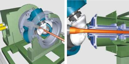
Figure 1 – Planetary three-roll stand PVP
The technological process of PVP in the planetary mill is implemented by means of a two-connected electromechanical system, namely, the system of electric drives of the rolls and the stand housing and the relationship between them. The electric drive of the screw stand includes two electric motors (Fig. 2), which are connected through a gear system with the roll and case mechanisms. The first engine, it is the main one, is used to rotate the rolls, this engine performs the main work of metal deformation. The stand housing with rolls located in it is driven around the rolling axis by an additional motor. The frequency of rotation of the stand body is regulated in relation to the frequency of rotation of the work rolls in such a way as to eliminate the rotation of the rolled product.
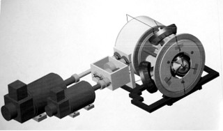
Figure 2 – General view of the planetary mill with electric drives of the rolls and the stand body
4. The concept of ACS TP for cross-helical rolling in a planetary mill
As it was determined earlier in the work, when the stand body stops and the rolls rotate, the usual process of deformation of the metal during its rotation should occur. Therefore, the electric drive of the rolls that carry out the deformation of the metal must be the main one and of greater power. And the drive of the stand body is an additional, adjustable low power, with the help of which the rotation of the pipe around the rolling axis is compensated. Consequently, the total power of the planetary screw stand, approximately equal to 700 kW, is divided into two drives: the main and additional drives with a ratio of 4/1, respectively.
Since it is impossible to accurately predict the initial ratio of the frequencies of the two motors, in which there would be no rotation of the pipe at the outlet of the planetary stand, therefore, the rotation of the pipe around the rolling axis will always be observed with some kind of creeping speed, which must be compensated. It is clear that the angle of rotation of the rolled products must be limited, controlled by an encoder with identification of the sign of its rotation. Due to the fact that the technological parameters of metal deformation are non-uniform, therefore, the roll will rotate at a non-uniform speed.
It is necessary to develop a control system for electric drives of a planetary three-roll stand in order to obtain a given workpiece reduction with a large drawing and to provide the possibility of combining the helical rolling process with the previous and subsequent stages of longitudinal rolling metal by compensating for the rolled product rotation by organizing an active adjustable yaw of the pipe around the rolling axis.
Figure 3 shows a concept diagram for constructing an ACS with electric drives for a BOP planetary mill. It follows from the diagram that the ACS of the BOP planetary camp contains the following local ACS:
⁃ ACS of rotation speed of planetary stand rolls;
⁃ ACS of rotation speed of the planetary cage body;
⁃ ACS for periodic movement of the pipe at the outlet of the planetary stand.
ACS of the speed of rotation of the rolls and the body of the planetary stand are implemented on the principle of feedback.
The electric drive of the rolls of the stand is the main one, therefore, it corrects the master action for the automatic control system of the electric drive of the planetary stand body in accordance with the initial speed ratio calculated on the basis of the second criterion of helical rolling. Setting the speed of rotation of the body electric motor is also corrected by the value of the additional yaw speed, which makes it possible to provide at the output a stable periodic movement of the pipe around the rolling axis with a minimum amplitude.
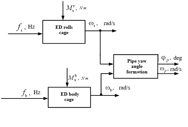
Figure 3 – The concept of building ACS by electric drives of the planetary mill BOP
(animation: 6 frames, 6 cycles, 52 KB)
Thus, the system of automatic control of the two-motor electric drive of the PVP planetary mill provides stabilization of the tube billet reduction process, and also compensates for the creeping angle of rotation of the tube at the outlet of the planetary stand by organizing its active yaw by subordinating the angular displacement of the tube billet to a controlled a priori given periodic motion with a very small amplitude relative to the rolling axis.
5. Analysis of the robustness of the developed ACS taking into account the main stochastic disturbances
Let us analyze the dynamics of the developed automatic control system for electric drives of the BRP planetary mill and the degree of its robustness under the influence of noise in the measurement circuit. The simulation will be carried out under the conditions of the scheme in Fig. 4, taking into account the connections from the blocks that emit interference from the angle sensor of the rotation of the tubular billet at the exit from the stand.
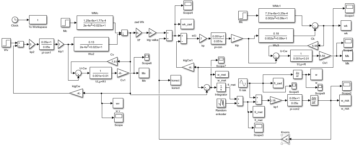
Figure 4 – Scheme for modeling the ACS by the BOP electric drive, taking into account interference
The transient characteristic of the angle of rotation of the tubular billet around the rolling axis is shown in Fig.5.
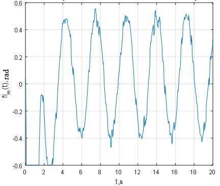
Figure 5 – Angle of rotation of the pipe billet around the rolling axis at the exit from the CHR stand
From the analysis of the transient response of the angle of rotation of the pipe billet around the rolling axis (Fig. 5), it follows that the movement of the pipe billet at the outlet of the planetary screw stand is accompanied by its periodic angular movement around the rolling axis, taking into account the noise component, the dispersion of which corresponds to the encoder error of 1, 5 deg. According to the transient response (Fig. 5), the additive noise component is very clearly visible, but the yaw angle does not go beyond 24.5 degrees (0.43 rad).
Figure 6 shows a graph of the rate of active yaw of the metal.
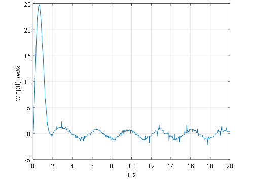
Figure 6 – Speed of active yaw of the pipe at the outlet of the CHR stand
The amplitude of the metal active yaw rate (Fig. 6), equal to +/-0.766 rad/s, corresponds to the metal yaw setting speed amplitude and the stand body electric drive rotation speed amplitude (Fig. 7). From fig. 7 it can be seen that the stand body yaws relative to its steady rotation speed, thereby compensating for the possible creeping angle of the workpiece at the exit from the stand.
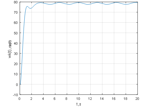
Figure 7 – Rotation speed of the CHR planetary cage housing drive
The transient characteristic of the electromagnetic torque of the body drive (Fig. 8) shows that a moment of 2 kN m is absolutely sufficient to overcome the moment of inertia of the entire stand, equal to 63 kg m2, taking into account the presence of interference.
Thus, based on the results obtained, it can be concluded that the proposed method for controlling the twin-engine electric drive of the BRP planetary stand is operational, the ACS of the planetary mill performs the task of tracking and stabilizing and meets the robustness conditions in the presence of noise from the tube billet position sensor.
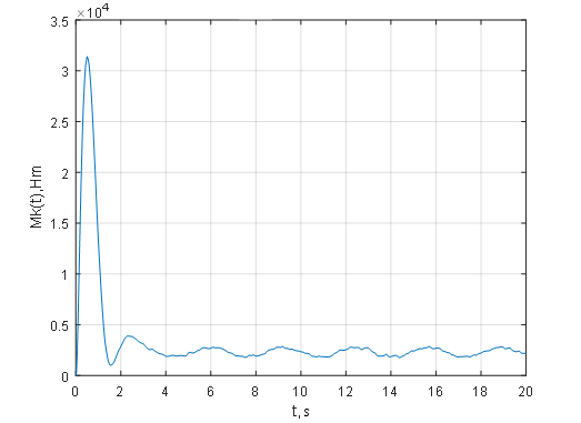
Figure 8 – Electromagnetic moment of the drive of the CHR cage body
6. ACS design
For a more complete and detailed understanding of the composition, purpose and principle of operation of the developed ACS for the electric drive of the planetary mill, taking into account the features and characteristics of the selected element base, a block diagram of the ACS hardware complex was developed, which is shown in Fig. nine:
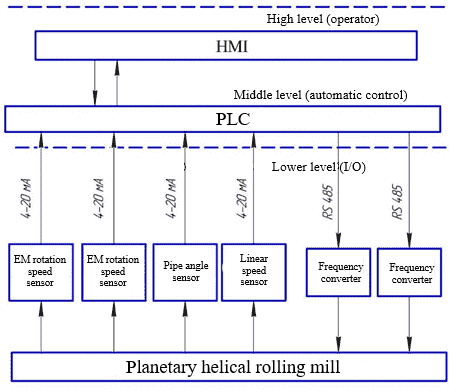
Figure 9 – Block diagram of a complex of technical means
According to the block diagram of the complex of technical means (Fig. 9), in the developed automatic control system for the electric drive of the planetary mill, there are three levels of hierarchy:
⁃ lower level - the level of sensors and actuators (sensors for the speed of rotation of the electric motors of the rolls, the stand body, the angle of rotation of the pipe, the linear speed of the entry of the pipe billet);
⁃ middle level - the level of control devices (industrial controller OWEN PLC 73);
⁃ high level is the level of devices for implementing the human-machine interface (OSEN PLC 73 operator touch panel with HMI).
The system operation algorithm is as follows:
⁃ lower level sensors (motor rotation speed, angle of rotation and linear speed) measure the corresponding values of the tubular billet and transmit them to the controller through the input / output device;
⁃ PLC, based on the data received from the sensors, according to a certain algorithm, generates a control action and sends it to the Modbus RTU network;
⁃ I/O device redirects this control action from the Modbus network to the frequency converter;
⁃ frequency converter, in turn, based on the received data, directly controls the actuator (electric motor). The converter controls the motor stator current vectors, which makes it possible, starting from zero speeds, to quickly control the motor torque.
Based on the results of the previous sections - the concept of building an automatic control system, a functional diagram of the automatic control system for electric drives of the BOP planetary mill was developed.
The functional diagram (Fig. 10) shows that the following control loops can be distinguished as part of the automatic control system for electric drives of the BOP planetary mill:
⁃ ACS of the speed of rotation of the rolls of the planetary stand;
⁃ ACS of the speed of rotation of the body of the planetary cage;
⁃ ACS for periodic movement of the pipe at the outlet of the planetary stand.
The SIARC software controller provides indication (I), alarm (A) and registration (R) of the measured and controlled value of the rotation speed of the electric motor of the planetary stand rolls, and also calculates and outputs the control action via RS485 to the frequency converter (FC) NS (2-2 ) frequency-controlled electric motor of the planetary stand rolls.
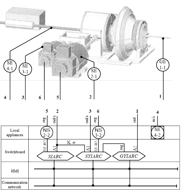
Figure 10 – Functional diagram of automatic control system for electric drives of the BRP planetary mill
The SYIARC software controller performs calculations (Y), indication (I), alarm (A) and registration (R) of the measured and controlled value of the rotation speed of the planetary cage housing electric motor, and also calculates and outputs a control action via RS485 to the frequency converter (FC) NS (3-2) frequency-controlled motor housing of the planetary stand.
The GYIARC software controller installed on the control panel implements the algorithm for controlling the periodic movement of the pipe at the outlet of the planetary stand based on information about its current value received from the GE angular motion sensor (1-1) and fed to the AI analog input of the GYIARC software controller.
Conclusion
The analysis of the technological process of cross-helical rolling in a three-roll planetary stand as an object of automatic control is carried out in terms of the main information variables for control.
The problem of the emergence of a creeping speed of the angle of rotation of the pipe billet around the rolling axis arises due to the inhomogeneity of the technological parameters of metal deformation and, as a result, the impossibility of accurately calculating the initial frequency ratio of the roll motors and the stand body, in which there would be no uncontrolled rotation of the metal. This problem is solved by organizing an active adjustable yaw of the pipe around the rolling axis at the exit from the stand.
Functional and structural diagrams of the complex of ACS technical means have been developed, which allows to fully implement the necessary functions of monitoring and regulating the system.
References
- Белевитин, В.А. Технология конструкционных материалов: обработка металлов давлением / В. Белевитин. – Чел: гос. пед. ун-та, 2015. – 184 с.
- Шимов Г.В. Основы технологических процессов обработки металлов давлением / Г. Шимов ред. С. Буркина. ? Ек: ун-та, 2014.? 160 с.
- Тартаковский Б.И., Ревес И.С.Патент Российской федерации №1448466 А1, кл. В21В13/20, В21В35/00. Стан поперечно-винтовой прокатки, заявл. 1987.01.07, опубл. 2000.04.10
- Э. Бретшнейдер, Планетарно-косовалковый стан [Электронный ресурс] / - Режим доступа: http://www.sms-meer.com
- Жукова Н.В., Литвинов В.И. Планетарный косовалковый стан, как объект автоматизации. /Збірник наукових праць ДонДТУ. Серія: Обчислювальна техніка та автоматизація, випуск 3. – Донецьк, 2007. – С. 6 - 13.
- Ф.Е. Долженков, А.Ю. Литвиненко., Проектирование профилировок валков клетей винтовой прокатки / – К.: Тэхника, 1992. – 135 с.
- Жукова Н.В. Кліть гвинтова тривалкова консольна обтискна. Патент на винахід № 92712 C2: МПК HO2P 9/00 /власник патенту Жукова Н.В., Литвинов В.І., Литвинова Т.С.-№а200901158;заявл. 13.02.2009;опубл. 25.11.2010,Бюл.№22.
- Башарин А.В., Новиков В.А. Управление электроприводами: Учебное пособие для вузов. – Л.: Энергоатомиздат, 1982. - 392 с.
- Ключев В.И. Теория электропривода: Учебное пособие для вузов., 2-е изд. перераб. и доп. – Л.: Энергоатомиздат, 1998. - 704 с.
- Магазинник Г.Г. Автоматизированные электроприводы и автоматические системы управления процессами металлургического производства. – Горький, 1981. - 50 с.