
Содержание
- INTRODUCTION
- 1. Relevance of the topic
- 2. Purpose and objectives of the study, planned results
- 3. Overview of research and development
- 3.1 Analysis of the technological process of a mine boiler plant with a low-temperature fluidized bed furnace as an automation object
- 3.2 Critical review of known technical solutions for the automation of a boiler plant with a low-temperature fluidized bed furnace
- 3.3 Justification of the direction of automation of a boiler plant with a low-temperature fluidized bed furnace
- 4. Development of the algorithm of operation and circuit solutions for the control system of a boiler installation with a low-temperature fluidized bed furnace
- CONCLUSION
- List of sources
INTRODUCTION
At present, despite the development of alternative sources for obtaining thermal energy, one of the main types of fuel is still solid fuel. The process of its utilization takes place in boiler plants. Currently, in order to increase the efficiency of solid fuel operation in boiler plants of mines, various resource-saving technologies are being introduced around the world, including a significant number of different methods of coal combustion being improved and re-developed.
Reducing the cost of heat production to supply industrial enterprises, including mines, today is an important and urgent task. Its solution is hampered by the use of low-efficiency heat generating plants and expensive types of fuels. In addition, the current practice of calculating the required heat supply at the enterprise using aggregated and averaged indicators and the rejection of predictive management of the performance of boiler units lead to significant overproduction of heat and the inability to respond in time to sudden changes in subscriber demand.
1. Relevance of the topic
The combustion process of solid fuel is a complex physical and chemical process, the control of which presents certain difficulties.
The fact that the enterprise's boiler plants are important technological facilities, emergency situations at which can lead to a shutdown of the entire production, it seems reasonable and obvious that it is necessary to conduct preliminary studies of the behavior of control systems for this facility using simulation models of these facilities to select the optimal structure and control laws. And, therefore, the issues of mathematical modeling and identification of such technological objects as low-temperature fluidized bed furnaces are of great scientific interest.
2. Purpose and objectives of the study, planned results
The aim of the work is to improve the operation of the NTKS boiler plant, by synthesizing the automatic control of the boiler unit, which will ensure the stability and trouble-free operation of the technological parameters of the furnace.
The overall goal of the work is specified by the following tasks:
– study of the flow of technological processes and their features of the boiler plant;
– analysis of existing technical solutions in the field of automation of NTKS boiler plants;
- improvement of the control system of the boiler plant of the NTKS furnace.
3. Overview of research and development
3.1 Analysis of the technological process of a mine boiler plant with a low-temperature fluidized bed furnace as an automation object
The main advantages of the low-temperature fluidized bed technology are the combustion of coal with an ash content of up to 70%, using substandard mine coal, the possibility of fully automating the operation of the furnace, the availability of several ways to quickly control its performance, and reducing emissions of nitrogen oxides into the atmosphere.
Low-temperature fluidized bed (LTCF) has been successfully used to burn lean coals. Consider the technology of solid fuel combustion in NTCS. Figure 1 shows the design of a boiler plant with an NTKS furnace. Fluidized (boiling) bed is a set of polydisperse particles through which the fluidizing air is blown at a certain speed sufficient for fluidization and not exceeding the rate of entrainment of fuel particles from the furnace. At the same time, the fuel particles are in a suspended state and are intensively mixed throughout the volume of the furnace, which improves the air supply to all fuel particles and intensifies the combustion process [1].
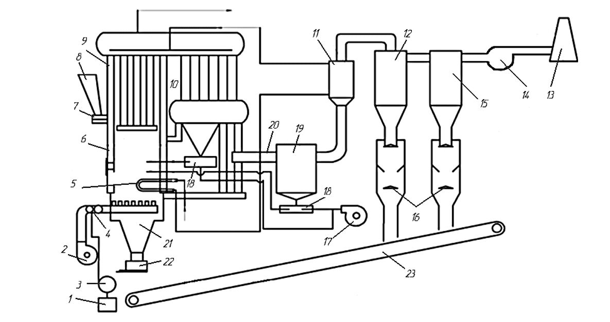
Figure 1 - Technological scheme of a mine boiler plant with a low-temperature fluidized bed furnace
In figure 1 it is indicated: 1 - container for liquid fuel; 2 - fuel pump; 3 - blower fan; 4 - kindling device; 5 - perforated pipe; 6 - firebox; 7 - fuel dispenser; 8 - fuel bunker; 9 - boiler; 10 - radiation heating surface; 11 - economizer; 12 - cyclone of the first stage of cleaning; 13 - pipe; 14 - smoke exhauster; 15 - cyclone of the second stage of cleaning; 16 - double dust shutters; 17 - fan return assignment; 18 - ejector; 19 - direct-flow cyclone; 20 - flue; 21 - ash bunker; 22 - ash unloader; 23 - ash removal conveyor.
Drawing air for bed liquefaction is supplied to the furnace through the air distribution grate using a high-pressure blower fan VMC-6 at a speed sufficient to boil the bed. For uniform distribution of air over the entire area of the furnace, air supply caps are installed with 6-8 holes for the passage of air, the speed of which at the outlet of the holes is 60-80 m/s. The design of the cap should exclude the ingress of slag or fuel into the air supply channels when the air supply is interrupted. Depending on the height of the layer, air must enter the furnaces with NTCS at a pressure of 3-10 kPa.
To achieve the required pressure, high-pressure fans of the VMC-6 type are used. The speed of air passing through the combustion mirror is 2.5-4 m/s, which is necessary for the layer to boil. The coefficient of excess air supplied to the furnace per 1 kg of coal is slightly higher than for layered furnaces, and is 1.2-1.6 theoretically required.
The air distribution grille is a set of pipes welded to the air distribution manifold, to which branch pipes with caps are welded, having holes around the perimeter through which air is supplied to the furnace under high pressure.
The air distribution grill performs several functions:
– ensures uniform distribution of the fluidizing agent over the entire cross section of the furnace;
– separates the fluidized bed from the rest of the space;
- contributes to the distribution of particles in the fluidized bed over the entire cross section of the furnace;
– ensures even distribution of fuel and removal of ash from the layer.
Fuel is supplied to the furnace from the fuel bunker from the front of the boiler using a ZP-600 caster, which is attached to the front plate from the ZP-RPK furnace. Moreover, the fractional composition of the fuel should not exceed 13 mm, which follows from the conditions of bed fluidization. The required fractional composition of the fuel is provided by using a crusher or screening unit at the stage of fuel preparation, and fuel with a fraction of up to 13 mm is fed into the coal bunker. Due to the fact that the size of the pieces of fuel supplied to the furnace does not exceed 13 mm, and the air velocities in the layer are increased, a large number of small particles of unburned fuel are carried away with the flue gases to the gas cleaning, where they are captured and returned to the furnace for afterburning.
For the uninterrupted and trouble-free operation of NTKS furnaces, maintaining the temperature and height of the layer is of great importance, which in the process of coal combustion is ensured by the timely removal of accumulated ash [2].
The most reliable and trouble-free in operation were swing-type unloaders, consisting of a table with an opening for spilling ash, a crank mechanism, a gearbox and an electric motor. The oscillating unloader table is installed under the ash storage bins. From the engine through the gearbox and the crank mechanism, the table receives reciprocating motion. Through the windows of the bunker, ash is poured onto the table, which, with the next movement, wakes up into the hole on the ash removal conveyor.
Due to the high intensity of the fuel oxidation processes in the fluidized bed, if heat is not removed from the bed, the particles of coal and filler are heated above the temperature at which the ash begins to soften, and the bed becomes slagged. To prevent this from happening, it is necessary to conduct the combustion process so that the temperature in the layer does not exceed the temperature at which the ash begins to soften.
It is most advisable to ensure the layer temperature is 800 - 850°C. Temperatures close to 800°C are determined by the most optimal conditions for the binding of sulfur oxides released from the fuel during combustion, dolomite and limestone, as well as alkaline earth metals contained in the fuel ash. At these temperatures, nitrogen oxide emissions also decrease.
Maintaining the temperature at a given level can be done in various ways:
- installation of additional submersible heating surfaces (HHP), recruited from pipes; water circulates inside the pipes, which heats up, taking away the heat of the layer; cooling of the layer by tubular surfaces immersed in it does not allow the temperature to rise above tash softening start temperature; ash sintering in this case does not occur and the layer remains in a mobile state;
- by supplying excess air, which is less economical;
– by supplying water (steam or other inert gases) to the layer;
– pneumatic transport to a layer of “cold” non-combustible solid particles.
Submersible surfaces, removing up to 50% of the heat released in the furnace, allow increasing the heating capacity of the boiler unit by 60% relative to the performance in the absence of PPN, as well as reducing the heating surface, which in turn reduces the dimensions and metal consumption when designing the unit. This is due to the high coefficient of heat transfer from the fluidized bed to the surface of the pipes immersed in it.
The combustion chamber is shielded from behind and from the sides by pipes with a diameter of 51x22.5 mm with a pitch of 100 mm, entering the collector with a diameter of 159x4.5 mm. The heating surfaces are made in the form of screen panels located along the walls of the combustion chamber. The convective-radiation surface consists of horizontal coil packs made of pipes with a diameter of 38x3 mm, located in the convective flue above the furnace.
The boiler is equipped with a failed single-pipe cap air grille. The grate consists of an air distribution manifold mounted on the bunkers, made of a pipe with a diameter of 426x9 mm, to which 128 branch pipes with a diameter of 38x3.5 mm with air distribution caps are welded. In caps with a diameter of 48 mm, 8 holes with a diameter of 7 mm are evenly located around the circumference for air outlet. The area of the combustion mirror is 2 square meters.
The one-pipe design of the grate simplifies its design and allows, by increasing the length of the nozzles, to use the heat of the drain ash for additional heating of the blast air.
Removal of slag from furnaces with LTCC does not cause difficulties, since pieces of slag, due to their high density, sink in the fluidized bed and collect in the lower part of the furnace. Slag removal devices must provide the necessary tightness.
At the perimeter of the combustion chamber, under the cap grate, a two-section metal hopper is installed, designed to accumulate and drain ash. The bunker is fixed on the boiler frame. The movement of water is carried out by forced circulation pumps, the temperature schedule of operation: 95 ... 700 ° С. The mains water flows to the rotary immersion heating surface and in parallel to the lower manifold of the rear screen.
Then, from the upper header of the rear screen, water enters the first upper parts of the upper headers of the side screens, from where, descending through pipes with a diameter of 51 mm, it passes the lower headers of the side screens and rises to the second part of the upper headers of the side screens. Then it enters the lower collectors of the convective surface. Water from the submersible heating surface also enters here. After passing the package of coils, the water is sent to the consumer. In order to avoid boiling, the average water velocity in individual elements of the boiler heated by radiation must not be lower than 1 m/s. Return network water with a temperature of 700°C comes from the suction systems of the network pumps, which feed it to the boilers, where it is heated to 950C and supplied to the external network by network pumps. The system is fed with chemically purified deaerated water from the make-up pumps to the suction line of the network pumps [3].
The raw water from the water supply is pumped to the heater, where it is heated up to 250°C and fed to the chemical water treatment plant (HVO). Softened water in the heater is heated to a temperature of 650°C and sent to a vacuum deaerator, from which it drains by gravity into a hermetic make-up water tank with a capacity of 3 square meters. The vacuum in the deaerator is created by liquid ring pumps.
To maintain the return water temperature at 700°C in order to prevent condensation of water vapor on the heating surfaces, leading to corrosion of the latter, a recirculation line with a temperature controller is provided in front of the boilers to supply part of the water from the direct to the return pipeline. A control valve is installed on the pipeline supplying softened water to the deaerator, operating from the water level in the make-up tank. Automatic dosing of make-up water is carried out by direct-acting pressure regulators “after itself” and “before itself”.
Measurement diaphragms are provided on pipelines of direct heating water from boilers to the main pipeline, which allow measuring and controlling water consumption [4]. Check and safety valves are installed on the same pipelines. Discharge of water when the safety valves are activated is provided in the cooling well. The lining of the boiler is made with 380 mm thick refractory fireclay bricks. The brickwork is framed by a frame to which the screens are attached.
3.2 Critical review knowntechnical solutions for the automation of a boiler plant with a low-temperature fluidized bed furnace
A well-known automation system for boiler plants is the automation of the process control system KONTUR [3]. The main function of automation of the KONTUR process control system is the safe automated control of the process equipment of the boiler unit in accordance with the technical regulations of the enterprise, in order to maintain the necessary technical and economic parameters of the equipment. Structurally, automation of the boiler control system is made in the form of a separate floor-mounted or wall-mounted cabinet. An operator panel and controls are installed on the front door of the cabinet. Inside the cabinet, the main module of the automation system and auxiliary elements (power supplies, fuses, intermediate relays, switching equipment) are installed.
The automation system of the KONTUR process control system is implemented by:
– feed water temperature control before and after the economizer;
– flue gas temperature control before and after the economizer;
– air pressure control after the blower fan;
– steam pressure control in the boiler drum;
– feed water pressure control;
– vacuum control in the boiler furnace;
– control of the water level in the boiler drum;
– control of the position of actuators;
– automatic regulation of the water level in the boiler drum;
– automatic regulation of steam pressure in the boiler drum;
– automatic control of air pressure in front of the burner, fuel-air ratio (fan motor frequency converter control);
- automatic regulation of vacuum in the boiler furnace (control of the frequency converter of the electric motor of the smoke exhauster);
– automatic control of salinity and automatic blowdown of the boiler;
- protection of the boiler in accordance with SNIP II-35-76.
Let's consider the operation of this system in more detail below.
The "Fuel" control circuit (Figure 2) contains a sensor (pressure gauge 56), a regulator (5v) and starting equipment (NS / KM11) for controlling a single-turn electric motor of the fuel supply control mechanism (5d - actuator).
Automatic adjustment of the fuel supply to the furnace is carried out according to signals from the steam pressure sensor, which is an electric pressure gauge RT / 56 with remote signal transmission (indications) to the RSK / 5v regulator. The pressure gauge converts the pressure of the steam supplied from the steam boiler drum into an AC electrical signal [3].
The “Air” control circuit consists of a sensor (pressure gauge 216), a regulator (21v), starting equipment (NS / KM12) for controlling a single-turn electric motor (21d) of the mechanism for turning the guide vane in the pipe supplying the blower fan.
The corrective signal to the regulators 5v and the twenty-first comes from the corrective device 5m (differentiating link), which, in turn, receives a signal from the sensor 5a (thermocouple). The corrective link acts as a feedback.
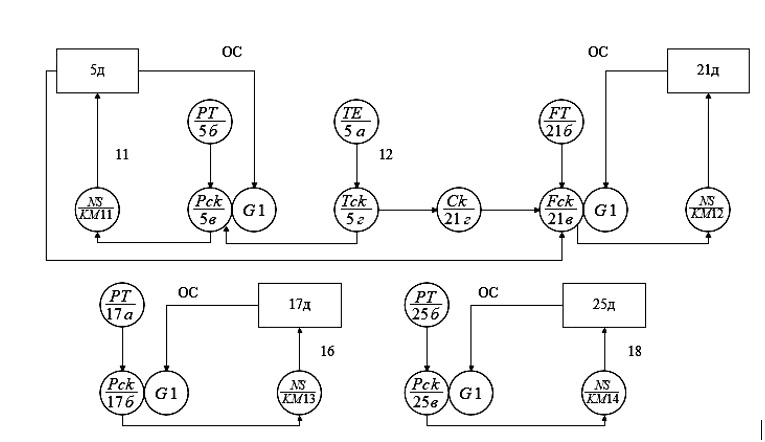
Figure 2 - Scheme of automatic control of the combustion process.
Vacuum control 176 maintains a constant vacuum with high accuracy. The vacuum pulse is taken in the upper part of the furnace by a sensor (draft gauge) 17a, which converts the vacuum into an electrical signal supplied to the regulator 176. From the regulator, the signal is fed to the starting equipment (NS / KM13) for controlling the single-turn electric motor of the actuator 17d for turning the guide vane installed in the pipe, supply smoke exhauster. When the vacuum in the furnace changes by an amount exceeding the insensitivity of the regulator amplifier, the electric motor of the actuator 17d moves the guide vane of the smoke exhauster until it restores this vacuum.
Adjustment of the "water level" is carried out by the regulator 25a, which receives an impulse from the level sensor 256 and acts on the actuator 25d, which is articulated with a controlled valve on the feed water pipeline. The level sensor is a pressure gauge 256, connected to the drum through a surge vessel 25a.
In the automation scheme, thermal control is carried out (Figure 2): boiler ignition temperature (2a, 26), fluidized bed temperature (36), flue gas temperature (1a, 16), air pressure after the blower fan (9), steam pressure (11), liquid fuel pressure in the inlet and pressure pipes of the fuel pump (12, 13), depression in the boiler furnace (18), depression in front of the smoke exhauster (20), water level in the drumnot boiler (246), fuel level in the bunker (26a), water temperature before and in the cooling circuit (6a, 8a), water pressure in the cooling circuit (15, 16), water flow through the cooling circuit (22a, 226, 22c) , fluidized bed resistance (31a). The protection circuit provides automatic shutdown of the fuel supply in case of emergency conditions, temperature increase in the fluidized bed, increase in pressure of the blast air, decrease in vacuum in the boiler furnace, deviation of the water level in the boiler drum, increase in water temperature in the cooling circuit, deviation of water pressure in the cooling circuit, reduction of water flow through the cooling circuit [3].
The disadvantage of automation of the CONTOUR process control system is the fact that all control loops have no connection with each other (open), that is, only the values ??specified by the operator affect the entire control process, but all the necessary parameters for this from others are not taken into account control loops. Thus, this system is not the most economical for the conditions of a non-permanent consumer and requires, in this case, constant adjustments from the operator, which can introduce errors associated with the human factor.
3.3 Justification of the direction of automation of a boiler plant with a low-temperature fluidized bed furnace
For the uninterrupted and trouble-free operation of low-temperature fluidized bed (LTCF) furnaces, maintaining the temperature and height of the layer is of great importance, which in the process of coal combustion is ensured by the timely removal of accumulated ash. It is most expedient to provide a bed temperature of 800-8500 C. Temperatures close to 8000 C are determined by the most optimal conditions for binding sulfur oxides released from the fuel during combustion, dolomite and limestone, as well as alkaline earth metals contained in the fuel ash. At these temperatures, nitrogen oxide emissions also decrease. Removal of slag from furnaces with LTCC does not cause difficulties, since pieces of slag, due to their high density, sink in the fluidized bed and collect in the lower part of the furnace. Slag removal devices must provide the necessary tightness.
Based on the technological features of the operation of NTKS furnaces, the developed system for automated control of the boiler plant and the distribution of thermal energy should perform the following functions:
– effectively burn low quality coal as the main fuel;
– regulate the performance of the NTKS furnace;
– regulate the supply of steam and hot water to all consumers according to their current temperature characteristics, categorization and trouble-free operation of the heat supply system, respectively [4].
Boilers equipped with mechanized devices for supplying and distributing fuel and slag and ash removal and having a certain furnace design are subject to automation. They automate the processes of combustion and power supply of the boiler unit, the processes of water treatment, slag removal, fuel supply, ash removal.
The following parameters are subject to monitoring and signaling:
– flue gas temperature (0-250°С);
– boiler ignition temperature (0-1100°С);
– fluidized bed temperature (+950°С);
– water temperature before and after the cooling circuit (70°С, 95°С);
– air pressure after the blower fan (3-5 kPa);
– alarm for vacuum in the boiler furnace (0.05 kPa);
– alarm for underpressure in front of the smoke exhauster (0.04 kPa);
– fluidized bed resistance alarm (4 kPa);
Automatic regulation of the fuel supply to the furnace is carried out according to signals from the steam pressure sensor, which is an electric pressure gauge with remote signal transmission (indications) to the regulator. The pressure gauge converts the steam pressure supplied from the steam boiler drum into an AC electrical signal. The “Air” control loop consists of a sensor (pressure gauge), a regulator, starting equipment for controlling single-turn electric motors, and a mechanism for turning the guide vane in the supply pipe of the blower fan. The corrective signal to the regulators comes from the corrective device (differentiating link), which, in turn, receives a signal from the sensor (thermocouple). The corrective link acts as a feedback [5].
Vacuum control maintains a constant vacuum with high accuracy. The rarefaction pulse is taken in the upper part of the furnace by a sensor (draft gauge) that converts the vacuum into an electrical signal that is fed to the regulator. From the regulator, the signal is fed to the starting equipment for controlling a single-turn electric motor, the actuator for turning the guide vane, installed in the supply pipe of the smoke exhauster. When the rarefaction in the furnace changes by an amount preincreasing the insensitivity of the regulator amplifier, the electric motor of the actuator moves the guide vane of the smoke exhauster until the set vacuum is restored [6].
The water level is regulated by a regulator that receives an impulse from a level sensor and acts on it with an actuator, which is articulated with a controlled valve on the feed water pipeline. The level sensor is a differential pressure gauge connected to the boiler drum through a leveling vessel. The scheme provides for remembering the cause of the accident. The emergency shutdown of the boiler is accompanied by a light and sound alarm.
In order to close all the loops of regulation and control of the technological process, it is necessary to improve this system by using the microprocessor controller OWEN PLC160 (M02) [7].
4. Development of the algorithm of operation and circuit solutions for the control system of a boiler installation with a low-temperature fluidized bed furnace
Before the development of the thermal control system of the mine boiler plant with the NTKS furnace, it is necessary to determine the input and output parameters of the device being developed.
So, the functions of the program are reduced to ensuring that the required temperature of the NTCS is reached by regulating the power of the NTCS furnace by the consumption of solid fuel In and, after exhausting the reserve of regulation for this parameter, by adjusting the flow of blast air by V.
As already noted above, the priority of regulating the furnace performance is given first to regulating the consumption of solid fuel, since this is much more economical. And we switch to regulating the flow of blast air only when the first means cannot provide the necessary control depth. In addition, the tasks of this program include the monitoring function so that the temperature of the NTCS does not exceed the limit values and, thus, prevents the state of an emergency situation, as well as the issuance of information on the computer about the exhaustion of reserves of both means of regulating the power of the furnace when the insert is not reached. This serves as a signal to the computer about the need to recalculate the power values for each furnace, taking into account the data received from all regulators.
Figure 3 shows a block diagram of the algorithm of the NTCS temperature control system.
After starting the system, the initial value of the temperature setting should be set Tcs.n., Tcs.v. Followed by a survey of temperature sensors Tcs.tech. Then the condition Tkc.tek>Tkc.v is checked (the current value of the temperature value is greater than the upper limit value of the NTCS temperature). If the current value still exceeds the upper temperature limit, then signals are generated to increase the fuel supply to the furnace and reduce the air supply flow. Then the cycle repeats and after a while the sensors are interrogated again for the current temperature value. If this condition is not met again, then signals are generated to reduce the fuel supply to the furnace and the constant value of the air supply flow rate.
When the condition Tcs.tech>Tcs.v is met, the current temperature value is checked by the following condition Tcs.tech
If the current value of the NTCS temperature corresponds to the conditions Tcs.tech>Tcs.v., and Tcs.tech.>Tcs.v., then the calculation of the "fuel-air" ratio is further determined. Gorenje process quality control can be carried out by the content of CO2 and O2. At the optimal value of the air flow coefficient in relation to fuel consumption, it is determined at the temperature of NTCS. Thus, the air supply control should be carried out with a fairly high accuracy and ensure a deviation of the CO2 value by no more than ± 0.5%. If Qtech - the current CO content coefficient2 is less than the specified coefficient, then a signal will be given to increase the air supply flow rate. With a large value of Qtech of the current coefficient, a signal is generated to reduce the flow rate of the air supply of the blast fan.
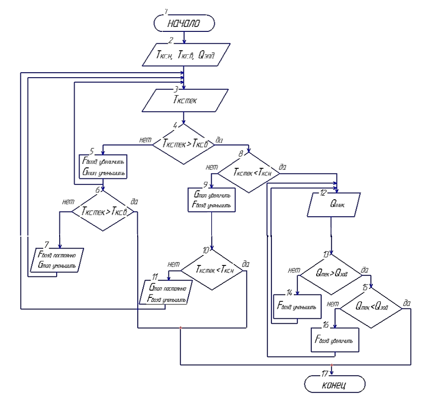
Figure 3 – Block diagram of the algorithm for the operation of the thermal control system of a mine boiler installation with a low-temperature fluidized bed furnace
In order to meet the advanced requirements for the temperature control unit being developed, it is necessary to develop a block diagram of this system. It is necessary to keep in mind the presence of a power supply unit, which provides the necessary levels and quality of the asking voltage, in the basic equipment, automation of the technological facility – the boiler plant, within which the system being developed will be used. The block diagram is shown in Figure 4.
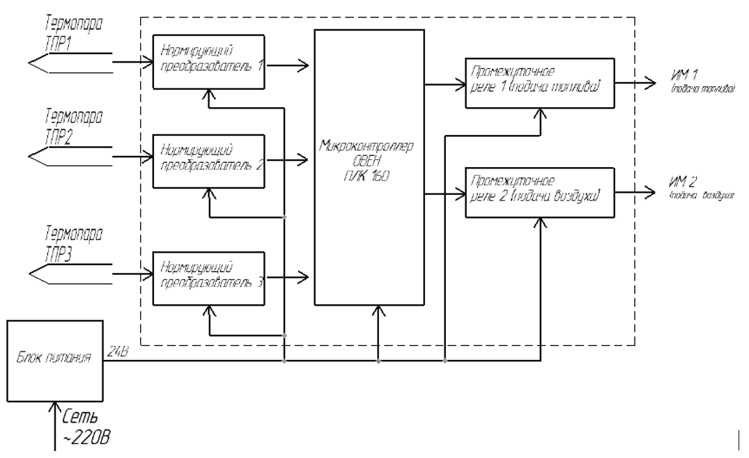
Figure 4 – Block diagram of the developed thermal regime control system in a boiler plant with a low-temperature fluidized bed
We are developing a functional scheme based on an already developed block diagram. The functional diagram of the thermal control system being developed for a boiler installation with an NTCS furnace is shown in Figure 5.
The developed functional scheme of the thermal regime control system consists of a channel for monitoring and signaling the state of the technological parameter - the temperature in the NTCS furnace.
In this case, the maintenance of the thermal regime of the mine boiler plant with the NTCS furnace controlled variables characterize the flow of the technological process.
The control device (UU), based on the measurement of controlled variables and setting influences, forms a control effect on the object of regulation. The adjustable value y(t) is the temperature in the NTCS furnace. This system is designed to maintain the required mode, i.e. temperature changes y(t).
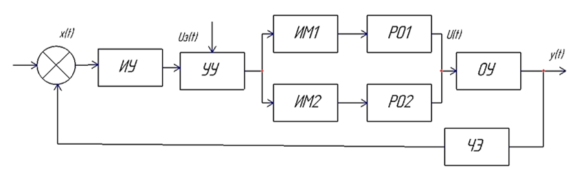
Figure 5 – Functional diagram of the developed control system for the thermal regime of a boiler installation with a NTKS furnace
The functional diagram also consists of a control object and a control device. The control object (OU) is the main element of the system, that is, the boiler plant, the set operating mode of which must be supported by a control device (controller PLK160 (M02)) with the help of regulatory authorities.
A control means a device that provides a control process, i.e. a purposeful action that leads to the desired change in the controlled variable (temperature of the NTCS). To reduce the control error, feedback is introduced into the system.
The control device is controlled by Uz(t) at the input of the system, forming a program for changing the controlled value. The control unit sends signals to the actuators (IM1, IM2) – single-turn electric motors, which is directly the corrective link of the system. The control action is adjusted depending on the output value y(t). the sensing element (CE) converts the controlled value into a proportional value and convenient for use in the ACS.
As this element, thermocouples are used, at the output of which a voltage proportional to the temperature of the NTCS is formed. Then this signal is supplied to the measuring device (IU). The control device performs the identification of the correspondences of the required and received values.
SUMMARY
Research and analysis of the process of solid fuel combustion in a mine boiler plant of a low-temperature fluidized bed were carried out. The processing of low-grade solid fuel into heat is especially effective and expedient specifically for the conditions of mine boiler plants with the subsequent use of the generated heat for own needs (shaft heating, heating of all mine buildings and structures), since it allows the use of own mine substandard fuel, coal preparation waste and at the same time no shipping costs.
The paper provides a critical review of technical solutions for process automation.
When writing this essay, the master's qualifying work has not been completed. The date of final completion of the work is June 2023. The full text of the work and materials on the topic of the work can be obtained from the author or his supervisor after the specified date.
List of sources
- Вискин Ж. В. и др. Сжигание угля в кипящем слое и утилизация его отходов. — Донецк: Новый мир, 1997. — 121 с.
- Махорин К. Е., Хинкис П. А. Сжигание топлива в псевдоожиженном слое. — К.: Наукова думка, 1989. — 204 с. — 196 с.
- Толпежников, Л. И. Автоматическое управление процессами шахт и рудников / Л. И. Толпежников. – Москва: Недра, 1985. – 352 с.
- Батицкий, В. А., Автоматизация производственных процессов и АСУ ТП в горной промышленности: Учеб. для техникумов / В. А. Батицкий, В. И. Куроедов, А. А. Рыжков. – Москва : Недра, 1991.
- Ткаченко А.Е. Повышение эффективности работы шахтного комплекса теплоснабжения при совместной работе котельных агрегатов НТКС на тепловую сеть: автореф. дис. кан. тех. наук. – Донецк; 2018. – 26с.
- Ткаченко А.Е. Определение параметров рационального функционирования группы котлоагрегатов НТКС на тепловую сеть шахты // Вестник Академии гражданской защиты. Выпуск 4 (12), 2017. С. 63-72.
- ОВЕН ПЛК 160. Контроллер программируемый логический. Руководство по эксплуатации. – 52 с.