
Abstract
Content
- Introduction
- 1. Relevance of the topic
- 2. Purpose and objectives of the study, planned results
- 3. Research and Development overview
- 3.1 Technological smelting of steel in an electric arc furnace as an object of automation
- 3.2 Development of the algorithm of operation and circuit solutions of the automatic control system of the technological mode of the electric arc furnace
- Conclusions
- List of sources
Introduction
To date, electric arc furnaces are considered the most common and environmentally friendly units for steel smelting. The possibility of concentrated input of a significant amount of thermal energy, combined with the ease of controlling the supplied electrical power, is an undeniable advantage of arc steelmaking furnaces compared to other steel production units.
1. Relevance of the topic
Reducing maintenance costs and extending the repair period, as well as simplifying troubleshooting, together with increasing reliability and efficiency, allows us to talk about a significant economic effect associated with the use of automation methods and tools proposed in the work in comparison with those traditionally used at the technological facility under consideration – an electric arc furnace.
That is why the research and design of a system for automating the processes of steel smelting in an electric arc furnace is an urgent topic at the present time.
2. Purpose and objectives of the study, planned results
The purpose of the study is to increase the efficiency of the electric arc furnace by developing an automatic control system that will improve the quality of the production while saving material and energy resources.
The main tasks of research:
- Analysis of the technological process of steel smelting in an electric steelmaking furnace as an object of automation.
- Development of structural and functional schemes of the automation system.
- Development of an algorithm for controlling the technological mode of an electric arc furnace.
3. Research and Development Overview
3.1 Technological smelting of steel in an electric arc furnace as an object of automation
The main purpose of controlling the melting process in an electric arc furnace is to obtain a metal of a given composition and a given temperature with high-performance and economical operation of the unit. This goal can be achieved if the management system successfully solves the following tasks:
- coordinated changes in the parameters of the melting process, i.e. the temperature and composition of metal and slag with the provision of the specified final values of the parameters at the outlet;
- maintaining a rational and economical electric mode of the furnace;
- preventing overheating and destruction of the lining and other structural elements of the furnace.
It is possible to increase the efficiency of the steel smelting process in an electric arc furnace by creating a modern automatic control system, updating hardware. The main tasks of automatic control of the melting process in an electric steelmaking furnace are:
- Centralized control of the technological process and operation of the furnace with the issuance of operational information to the furnace maintenance personnel with registration and alarm of deviations from the set values of the main parameters.
- Process control – calculation of the optimal composition of the charge; control of the charge loading in accordance with the calculated composition; calculation of the amount of oxygen, alloying and slag-forming materials, ensuring the production of metal of a given composition and quality and saving materials; control of the supply of alloying and slag-forming materials; control of oxygen supply to the bath; prediction of the end of the technological periods of melting.
- Control of the energy regime, ensuring maximum use of the furnace power, minimum electricity consumption and normal operation of the furnace and its electrical equipment – control of the thermal regime, control of the electrical regime, control of gas-oxygen burners, control of the exhaust gases from the furnace.
- Management of auxiliary operations – metal sampling, metal temperature measurement, etc.
- Collection and selection of information with the issuance of necessary documentation – accounting and registration of costs of charge materials, alloying, electricity, oxygen; printing of melting protocols, etc.
- Monitoring the operation of equipment with alarm and fault registration.
Modern automated control systems of steel are developed on the basis of the classical three-level model of building the architecture of the system:
- lower – field level (sensors);
- medium – the level of basic automation of production processes (control controllers);
- upper – technology management level.
On the lower level there is field equipment: sensors, actuators and their secondary devices, control station shields. The tasks of this level of equipment include measuring physical parameters and converting them into standard types of electrical signals, receiving control signals from medium-level equipment (controllers) and direct control of technological equipment in accordance with these signals.
The control level is created using high-performance programmable logic controllers with a distributed I/O system.
The first two levels are designed using modern software and hardware from leading foreign and domestic manufacturers of automated control system components (Siemens, Schneider Electric, Bernecker &Rainer, ABB, Omron, etc.), control and dispatch control systems (SCADA systems) are developed on the basis of software products Siemens WinCC, Schneider Vijeo Citect, WonderWare InTouch, Bernecker&Rainer, et al.
To automate the chipboard-150 of the Siemens VAI design (Germany), a PLC system platform was used to control the technological processes of the entire steelmaking shop as a whole - SIEMENS SIMATIC S7 (Fig. 3.1).
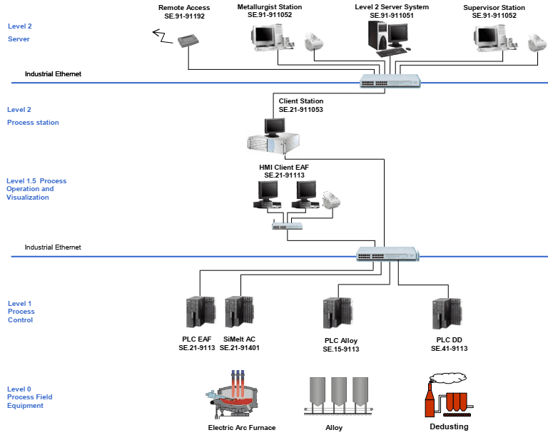
Figure 3.1 – Block diagram of DSP-150 automation
The automation system level is able to control the equipment without any other higher-level system. The automated process control system includes the following components as far as they are specified in the scope of delivery specification:
- Human-machine interface (HMI);
- Programmable logic controllers (PLCs);
- weighing equipment;
- special nodes based on microprocessor technology;
- remote control and/or panels in the control post(s).
The Level 1 system covers all the necessary functions for controlling the equipment in manual and/or automatic mode. Data transmission between the Layer 1 system and higher-level systems is provided either through a bus system or through standard serial communication channels.
Manual control of individual units or groups of units (start/stop) or manual adjustment of valves, throttle valves, actuators, etc. is performed from remote controls or control panels in the control post(s). In this mode of operation, only the basic locking functions function to prevent danger to operating personnel and mechanical equipment.
Automatic mode provides control functions without feedback and/or with feedback and control of equipment with all locks via HMI (for example, manual adjustment of setpoints) and traditional controls as needed to control the equipment. The purpose of the operation of the arc steelmaking furnace is to obtain metal with a temperature of 1620 ° C ± 20 ° C with the necessary composition and the required quality [1,3].Steel smelting in chipboard includes the following technological operations [1,3,4]: preparation of the furnace for filling; filling; melting; finishing; release of melting.
In the charge span of the ESPC, the metal charge is loaded into baskets (buckets) and is delivered to the furnace span of the ESPC with the help of a bridge crane, where it is filled into an arc steel furnace. Steel smelting begins with the filling of the metal charge on the "swamp", remaining from the previous melting of a part of the liquid metal in the amount of 15 tons. A lightweight scrap is placed at the bottom of the loading bucket, then a heavy scrap is placed. Slag-forming additives are loaded closer to the walls of the bucket. Coke is laid on top of a layer of heavy scrap and lime to prevent electrode breakdowns in contact with conductive materials. Then a layer of lightweight scrap is placed on the middle scrap to quickly melt the wells. The dense laying of the metal charge ensures its good conductivity. If it is impossible to load coke or slag-forming materials into the bucket, they are filled into the chipboard during the melting of the filling.
Steel smelting is carried out in automatic mode, under the influence of thermal exposure. The conversion of electrical energy into thermal energy occurs when an electric arc occurs, which is one of the types of arc discharge that occurs between graphite electrodes. It is the magnitude of the arc current and the distance between the electrodes that determine the melting rate of the metal. After the filling is completed and the chipboard arch is installed in the working position, the electrodes are lowered almost to touch the charge and the furnace is turned on. Electric arcs light up between the electrodes and the charge, under the influence of radiation from which the metal charge begins to melt under the electrodes and the liquid metal flows down. To accelerate the melting of scrap in cold places of the working space and to obtain an active slag bath over the entire surface, additional energy of oxygen-gas burners is used, the gas and oxygen consumption per burner is taken in a ratio of 1:2. The burners are turned on immediately after filling, when working with wall oxygen-gas burners, also bottom purging with argon is carried out to improve the quality of the metal.
The electricity consumption during the melting period is 370 kWh/t. During the operation of the chipboard, it is necessary to maintain a constant electric arc. To do this, it is necessary to organize proper conductivity between the electrode and the charge. The required level of conductivity is achieved by changing the position (movement) of the electrodes vertically, or by changing the voltage on them, a voltage from 100 to 600 V and a current of 50-100 kA is applied to maintain the arc. The electrodes are gradually moved and lowered into the "wells" formed under them in the charge. During the melting process, the temperature of the water on the panels of the vault is controlled.
At the time of intensive slag formation and the descent of slag from the furnace, the temperature of the metal should be 1550oC, which allows to obtain the best conditions for dephosphorization of the metal. For the slag to descend, the chipboard body is tilted towards the working area of the materials by about 5o. Slag removal is carried out through the chipboard working window. In order to prevent overoxidation of the bath during the operation of oxygen tuyeres and purging of the bath with oxygen, the supply of carbon-containing material is mandatory. At the moment of complete melting of the metal charge, the temperature of the metal is measured with a thermocouple and sampling is carried out with an immersion sampler. Having received preliminary information about the chemical composition of the metal, the oxidation of impurities in the metal is continued by purging the chipboard bath with oxygen through an oxygen lance.
The process of melting steel into chipboard, as well as the preceding and subsequent stages of this technological process, are accompanied by significant dust emissions. The removal of furnace gases from the chipboard is carried out through a water-cooled flue and a gas cleaning system with bag filters. The release of the finished metal is carried out through a drain chute. The whole process of controlling an arc steelmaking furnace and its elements is divided into technological mode control and thermal mode control [5,6]. Since in the electric steelmaking technological process in chipboard, the bulk of the heat is obtained as a result of the conversion of electrical energy, it becomes necessary to control the amount of incoming heat, i.e. the electrical mode, or more precisely, the electrical power of the chipboard [6,7].
The analysis of the features of the steel smelting process performed above made it possible to draw up a structural diagram of the material flows of chipboard, which is shown in Fig. 3.2.
As follows from the scheme of material flows of the chipboard (Fig.3.2) and the above analysis of the technological processes occurring in it, an electric steelmaking furnace is a complex, multidimensional, multi-connected control object consisting of a large number of technological elements. The first and main technological element and process, without the normal functioning of which it is impossible to imagine the work of a chipboard in principle, is the process of obtaining thermal energy from electrical energy due to the required maintenance of the length of the electric arc at various stages of the melting process. As described above, this is the main process in controlling the chipboard – controlling the thermal mode of the chipboard, which is reduced to controlling the electrical mode, or rather, the electrical power of the chipboard, as a rule, by changing the arc length [6,7].
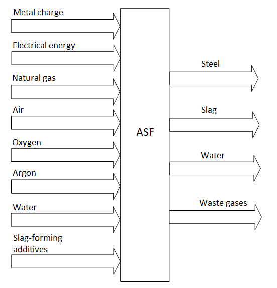
Figure 3.2 – Block diagram of material flows of ASF
The next technological element of the chipboard, which determines the efficiency and cost-effectiveness of the steel smelting process, is an oxygen tuyere [7,8]. The normal functioning of the oxygen lance is determined by maintaining the required parameters of the oxygen supply process and its cooling process. The process of oxygen supply to the working space of the chipboard is characterized by the necessary oxygen consumption for purging while maintaining its required pressure. The deviation of oxygen flow and pressure from the required values leads to an increase in the operating costs of the steel production process in chipboard or to a deterioration in the quality of the steel obtained. When cooling the tuyere, it is necessary to change the cooling water flow rate to maintain the required temperature difference at the outlet and inlet of the oxygen tuyere, which, at a relatively constant temperature of the cooling water, reduces to maintaining the set temperature of the cooling water at the outlet of the oxygen tuyere.
Thus, based on the scheme of material flows of the chipboard (Fig.3.2) and the above-discussed features of the process of moving the electrodes, the cooling process of the oxygen tuyere, as well as the oxygen supply process, a diagram of an arc steelmaking furnace for the listed elements as an object of automatic control is obtained, which is shown in Fig. 3.3.
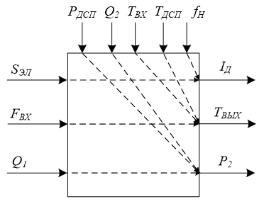
Figure 3.3 – ASF as an object of automatic control
The controlled variables characterizing the functioning of the main technological elements and processes during the smelting of steel in chipboard are (Fig. 3.3):
- when controlling the power of the chipboard – electric arc current ID;
- when controlling the cooling of the oxygen tuyere – the temperature of the cooling water at the outlet of the tuyere;
- when controlling the oxygen supply to the tuyere, the pressure at the inlet to the oxygen tuyere (at the outlet of the oxygen supply pipeline) P2;
The control actions that allow the required way to influence the listed controlled variables are (Fig. 3.3):
- when controlling the power of the chipboard – moving the SEL electrode;
- when controlling the cooling of the oxygen tuyere – the flow of cooling water at the entrance to the oxygen tuyere FXX;
- when controlling the oxygen supply to the tuyere, the oxygen consumption at the outlet of the controlled valve (at the inlet of the supply pipeline) Q1;
Disturbing influences for the considered elements of the chipboard are (Fig. 3.3):
- when controlling the power of the chipboard – uncontrolled disturbances of the electrical regime that change the distance between the electrode and the metal charge fH (disturbances of the electrical regime occur when the metal charge collapses during melting; when the metal boils; when the electrodes burn; when the metal level rises as it melts);
- when controlling the cooling of the oxygen tuyere – the temperature of the cooling water at the entrance to the oxygen tuyere TVX and the temperature in the working area of the chipboard TDSP;
- when controlling the oxygen supply to the tuyere, the oxygen consumption consumed by the oxygen tuyere (at the outlet of the oxygen supply pipeline) Q1 and the pressure in the working area of the chipboard RDSP;
The analysis of the technological scheme, technical features, operating modes, means and systems of automation of technological elements and processes of chipboard allows us to formulate a goal – to increase the efficiency of the electric arc furnace by developing an automatic control system, which will improve the quality of products while saving material and energy resources.
We formulate the requirements for the control system of the technological mode of the electric arc furnace based on the FURPS+ model, such as: Functionality - functionality; Usability - applicability; Reliability - reliability; Performance - performance; Supportability - serviceability.
1. Functionality:
- collection, primary processing, distribution and formation of arrays of information received from sensors of technological and energy parameters of the electric arc furnace in the form of analog, discrete and digital signals;
- presentation of information and user interaction with the software and hardware complex of the electric arc furnace;
- remote control of drives of equipment and actuators of electric arc furnace;
- automatic, software-controlled electric arc furnace;
2. Security.
Electrical products used in the control system of an electric arc furnace must comply with GOST 12.2.007-75, and computer equipment – according to GOST 25861-83, and have class 1 protection of a person from electric shock. All external elements of the technical control system that are energized are protected from accidental touch;
3. Applicability.
The workplace of the operator of the electric arc control system of the steelmaking furnace must contain several workstations that are designed for:
- presentation, storage and processing of technological information;
- performing functions and tasks of a settlement nature;
- implementation of system-wide functions;
4. Reliability.
The software and hardware complex of the electric arc furnace in terms of reliability requirements must comply with GOST 4.148-85, GOST 24.701-86 and GOST 27.003-90.
5. Performance.
Performance indicators, response time, accuracy and reliability of information should be no worse than existing analogues.
6. Serviceability.
The suitability for operation is characterized by:
- operating ambient temperature 5-50°C;
- limit temperature 0-100°C;
- relative humidity of 30-75% at a temperature of 25 ° C;
7. Requirements for weight, dimensions and degree of protection of the housing.
ACS units should be factory-made products with standard or design-component tactical and technical, metrological and mass-dimensional characteristics.
According to the degree of environmental protection:
- instrument cabinets KP TM – not lower than IP55 (IP65);
- control panel – not lower than IP21;
- server equipment cabinet – not lower than IP21;
3.2 Development of the algorithm of operation and circuit solutions of the automatic control system of the technological mode of the electric arc furnace.
The control of the electric mode of the furnace of the electric arc furnace is divided into several stages (Fig. 3.4):
- Sinking the electrodes into the charge.
- Melting wells.
- Metal melting.

Figure 3.4 – Block diagram of the algorithm for controlling the technological modes of the electric arc furnace
Before the stage of sinking the electrodes into the charge, the furnace arcs are ignited. The differential control method provides automatic ignition of arcs. After switching on the furnace in the absence of current, the electrode goes down until it touches the metal. When a signal appears on the current sensor, the first electrode stops. The second electrode begins to descend, when the metal touches the second electrode, both electrodes rise up, igniting arcs. And the third electrode goes down until it touches the metal, after the current appears in it, it will begin to rise, igniting the third arc.
The first stage is the sinking of the electrodes into the charge. At the moment of arc ignition, the current position of the electrodes is fixed. The value of the electrode sinking is programmatically set, when the current value of the electrode sinking reaches the set value, the control system switches to the next mode – sinking wells.

Continuation of Figure 3.4 - Block diagram of the algorithm for controlling the technological modes of the electric arc furnace
The stage of melting wells. At this stage, the electrodes pass through the well quickly, and liquid metal is formed. Limit switches are provided to limit the movement of the electrodes to the extreme position. A signal about the absence of movement of the electrodes will indicate the end of the melting period of the wells, and the transition to the melting stage of the metal.
The metal melting stage takes place when the maximum power is introduced into the furnace. This stage is completed during the period when the metal temperature reaches the set program value.
The designed automation system in its structure represents a distributed automated control system. Applying modern principles of construction, it is possible to determine the following structure of the automation system (Fig. 3.5):
- dispatcher level – responsible for collecting, processing data and displaying the technological process;
- the level of controllers and I/O modules, at this level, primary information will be collected and processed from the lowest level;
- the level of sensors and actuators, at this level, the sensor signals are coordinated with the inputs of the control device, and the commands generated with the actuators.
For the designed automation system, it is necessary to install primary sensors for measuring the temperature of the lining and masonry of the bottom, measuring the temperature of liquid metal. A sensor for measuring the temperature of the cooling water in the pipeline used for cooling the furnace elements, as well as measuring the temperature at the drain from the water-cooled panel, by the temperature difference at the inlet and outlet of which, it is possible to judge the intensity of the cooler, and accordingly regulate the flow of cooling water using an actuator with a flap, as well as a temperature sensor for exhaust gases.
For the automation system, it is necessary to monitor the oxygen flow rate on the tuyere using pressure and flow sensors, as well as to control the flow rate on the tuyere by means of an actuator and install a shut-off valve in order to prevent emergencies.

Figure 3.5 – Block diagram of the ASF automatic control system
The value of the operating current in each phase at the selected supply voltage stage depends on the arc length. The operating current is controlled by moving the electrode, which is controlled by a position sensor, and it is also necessary to take readings from the primary devices of the current and voltage sensor.
All information collected from primary devices (sensors) is sent to the controller level, represented by analog unified current signals of 4-20 Ma. To control the actuators, an analog unified signal of 4-20 mA should be used. Twisted pairs of Ethernet are used to connect the PLC with the upper (dispatcher) level.

Figure 3.6 – Functional diagram of the ASF automation system
Conclusion
The technological process of steel smelting in an electric arc furnace as an object of automation was considered. The structural and functional schemes of the automation system, as well as an algorithm for controlling the technological mode of an electric arc furnace, have been developed. When writing this abstract, the master's work has not yet been completed. Final completion: June 2023. The full text of the work and materials on the topic can be obtained from the author or his supervisor after the specified date.
List of sources
- Сведчанский, А.Д. Электрические промышленные печи: Дуговые печи и установки специального нагрева: учебник для вузов. / А.Д. Сведчанский, И.Т. Жердев, А.М. Кручинин – 2-е изд., перераб. и доп. – М.: Энергоиздат, 1981. – 296 с.: ил., табл.
- Поволоцкий, Д.Я. Электрометаллургия стали и ферросплавов. / Д.Я. Поволоцкий – М.: «Металлургия», 1978. – 550с.
- Окороков, Н. В. Электроплавильные печи черной металлургии. / Н.В.Окороков – М.: Металлургия, 2005. – 220 с.
- Марков, Н.А. Электрические печи и режимы дуговых электропечных установок. / Н.А. Марков. – М.: Энергия, 2003. – 204 с.
- Пирожников, В.Е. Автоматизация контроля и управления электросталеплавильными установками / В.Е. Пирожников, А.Ф. Каблуковский – М.: «Металлургия», 1974. – 208 с.: ил., табл.
- Лапшин, И.В. Автоматизация дуговых печей. / И.В. Лапшин – Москва, 2004. – 166 с.
- Глинков, Г.М. АСУ ТП в черной металлургии: учебник для вузов. / Г.М. Глинков, В.А. Маковский – 2-е изд., перераб. и доп. – М.: «Металлургия», 1999. – 310 с.
- Глинков, Г.М. АСУ технологическими процессами в агломерационных и сталеплавильных цехах: учебник для вузов. / Г.М. Глинков, В.А. Маковский – М.: «Металлургия», 1981. –360 с.: ил., табл.
- Кисаримов, Р.А. Электропривод: справочник. / Р.А. Кисаримов, Москва, ИП РадиоСофт, 2008.- 391 с.
- Терехов, В.М. Системы управления электроприводов: учебник для студ. высш. учеб. заведений / В.М. Терехов, О.И. Осипов; под ред. В.М. Терехова. - 2-е изд., стер. - М.: Издательский центр «Академия», 2006. - 304 с.