
Abstract
Content
- Introduction
- 1. Theme urgency
- 2. Goal and tasks of research, expected results
- 3. An review of research and development
- 3.1 Analysis of technological process of drying bulk materiakl in drying drum oven as an object of automation
- 3.2 Drying drum furnace as an object of automatic control
- 3.3 Analysis of existing development in the automation of the drying drum oven
- 3.4 Justification of the direction of automation of the drying drum oven
- 3.5 Alogrithmisation of operation and schematic solutions for automatic control system of the drying drum oven
- Conclusions
- References
Introduction
The removal of liquids (solvents) from the surface or internal layers of various materials is widespread in various branches of the economy and manufacturing industry. The liquids retained but the materias cand be water, methanol, petrol, methanol – acetone mixture, petrol – izopropyl mixture, e.t.c. Among the existing methods of dehydration of materials (drying, pressing, centrifugation, filtration, suction, chemical absorption, etc.) a special place is occupied byt thermal drying, in which the removal of moisture from the materials occurs, mainly, by evaporation
Drying – is a thermal process for dehydratin of solid materials by evaporting moisture and removing the resulting vapors. Wherein, in the substance there is a transfer occurs in the substance and diffusion movement of moisture. The duration of the drying is determined by the time interval, required to reduce the moisture content from the initial value to the final.
1. Theme urgency
The purpose of controlling the drying process is to ensure that the incoming wet solid material is dried to a predetermined moisture context.
Dehydration of materials, including drying, is intended to improve their quality and durability, e.g. when drying wood, increasing the heating value when drying fuel, the possibility of long–term storage when drying foodstuffs, etc. Therefore, in some cases drying is accompanied by structural, mechanical, chemical, biochemical, rheological changes in the dried material.
The speed of these processes, the degree of their competition depends not only on the method of heat supply to the material, but also on drying mode.
A distinction is made between natural (outdoors) and artificial (in dryers) drying. In natural drying, the material can be dried only to moisture content close to the equilibrium. The advantage of artificial drying is its short duration and the ability to regulate the final moisture content of the material. Apparatuses in which drying is carried out are called dryers. According to the method of heat communication, convective, contact, thermo–radiation, sublimation and high–frequency dryers are distinguished. Dispersed materials, which include granular, powdered, granular, crushed solids, as well as dispersed liquid and paste products in the chemical technology is dried mainly by convection drying.
If the contact of the dried material with air oxygen is unacceptable or the vapors of the removed moisture are explosive or flammable, then the drying agent is gases inert to the dried material: nitrogen, carbon dioxide, helium and other inert gases or superheated water vapor.
2. Goal and tasks of research, expected results
The purpose of the study is to improve the efficiency of high – quality technological process of drying bulk material in drying drum oven by developing an automatic control system, also well as control and regulation of the main technological parameters of this control object.
Main tasks of research:
- Analysis of technological process of drying bulk materiaks in drying drum oven as an object of automation;
- Presentation of drying drum oven scheme as object of automatic control;
- Analysis of existing development in the automation of the drying drum oven;
- Justification of the direction of automation of the drying drum oven;
- Alogrithmisation of operation and schematic solutions for automatic control system of the drying drum oven.
3. An review of research and development
3.1 Analysis of existing development in the automation of the drying drum oven
The main task of controlling the drying of bulk materials in drying drum oven is to ensure the drying of the incoming solid material is dries to predetermined moisture content. The main disturbances in the process are changes in flow rate, initial moisture content and particle size distribution of the solid material as well as changes in flow rate and initial temperature of the drying medium. The main controlled variable of the process is the residual moisture of the solids, which is directly dependent on the drying temperature. The process control of the drying drum oven must therefore be automated in order to achieve an adequate drying quality.
The control criterion (performance indicator) of the process is a parameter that determines the quality of the product or its quantity.
Temperature mode of drying is regulated depending on the humidity and temperature of the materials, which are controlled by samples taken through the hatch of the expansion chamber.
After reaching the required temperature regime, the moisture content of the material is controlled. If it is higher than 7 % (required moisture content), this means that the initial moisture content of the materials is high and they must be dried in more than one pass through the drying drum oven.
Depending on the humidity and the amount of material, the amount of the air – gas mixture required for drying will also change. Therefore, the suction fan (flue gas aspirator), which is installed downstream of the cyclone, must also be controlled in order to maintain the correct velocity of the gas/air mixture (vacuum in the drying section).
Fig. 1 shows the design of drying drum oven
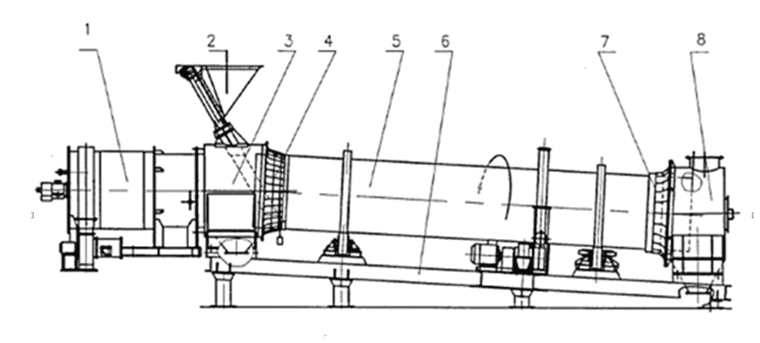
Figure 1 – Design of drying drum oven
The material is loaded into the drying drum (pos. 5) through a screw feeder and a loading pipe installed on the loading chamber (pos. 3). The drum dryer is installed at an angle of 3° – 5° to the horizontal and can rotate around the longitudinal axis at a speed set by a frequency converter, which can control the rotation speed of the drive motor.
The material sequentially passes through these components of the unit and, as it moves to the unloading chamber (pos. 8), moisture evaporates from it. The coolant, in this case the gas–air mixture formed in the heat generator (pos. 1), moves to the unloading chamber under the influence of vacuum. The vacuum is created by an exhaust fan (smoke exhauster), which is not part of the drying unit and must be installed after the unloading chamber. In this technological process, drying is carried out by the direct flow method, that is, the material and the coolant move in one direction.
The material entering the dryer drum is constantly moving along the axis of the drum, while being mixed and constantly in contact with the coolant.
To regulate the amount of material fed by the screw feeder (pos. 2), the rotation speed of the screw feeder drive motor is also controlled by the frequency converter.
As you move towards the unloading chamber, the material is dried. Moisture from the material is carried away by the heat carrier to be cleaned from the dusty fraction of the material entrained by the heat carrier.
The temperature of the gas–air mixture supplied from the heat generator should not exceed 900 °C. The temperature of the outgoing gas–air mixture must be at least 100 °C, in order to avoid the formation of condensate in the discharge part of the dryer drum. The moisture content of the material entering and exiting the dryer must be periodically monitored to control the operation of the dryer. The temperature regime of drying is regulated depending on the humidity and temperature of the materials, which are controlled by samples taken through the hatch of the expansion chamber. After reaching the required temperature regime, the moisture content of the material is controlled. If it is higher than 7% (required humidity), then this means that the initial moisture content of the materials is increased, and they must be dried in more than one pass through the drum dryer.
Depending on the quality of the processed raw material, its type, the most optimal design of the drying drum, its size, the necessary heat engineering calculations should be selected. The drums can have a capacity from 150 kg to 100 tons per hour, which will determine the dimensions of the loading chamber, the unloading chamber, the power of the heat generator, the features of the dust and gas cleaning mechanism, as well as the supply and removal of the coolant. Such equipment can differ in the way the material is fed (mechanical or pneumatic), as well as in the number of drums in the installation (maximum three).
In order to control the drum dryer, it is necessary to have a certain central control point from which the necessary technological parameters will be remotely controlled, as well as control of fuel consumption and other physical quantities.
3.2 Drying drum furnace as an object of automatic control
Fig. 2 shows the structure scheme of drying drum oven as an object of automatic control
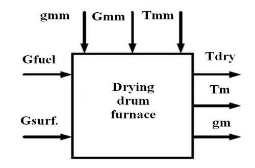
Figure 2 – Drying drum oven as an object of automatic control
The moisture content of a dry material gwm is determined, on the one hand, by the amount of moisture that comes with the wet material and, on the other hand, by the amount of moisture that is removed from it during the drying process. The amount of moisture that comes with the wet material depends on the consumption of that material and its moisture content, as well as the consumption of the drying agent.
Moisture Рmm in drying drum oven can easily be stabilised by changing the drying agent Gmm flow rate, which is removed from the dryer. The temperature is determined by all available parameters, and also by the intensity of the process of evaporation of moisture from the material. It can be stabilised by changing the flow rate Gfuel or temperature Tdry of drying agent. It should be noted that the range of variation of the last parameter is significantly limited, which is explained by safety requirements.
Complete combustion of the fuel gas is ensured by an automatic fuel gas to primary air ratio control system which controls the primary air supply to the furnace. If the calorific value of the fuel changes, it is advisable to correct this ratio for the oxygen content of the flue gases.
Let us formulate the requirements for an automatic control system for the operation of a drying drum oven based on the FURPS+ model, such as: Functionlity; Usability; Reliability; Performance; Supportability
- Funсtionality:
– Collection, primary processing, distribution and formation of information received from the process and energy sensors of the drying drum furnace in the form of analogue, digital and discrete signals;
– presentation of information and user interaction with the drying drum furnance's software and hardware system;
– remote control of the machinery and actuators of the drying drum furnance;
– automatic, software – drive control of the drying drum furnance system;
– vacuum discharge control after the battery cyclones (P = 0, 5 кPа).
- Safety:
All electrical products used in the tamble drying drum furnance must comply with GOST 12. 2. 007 – 75, аnd computer software – with GOST 25861 – 83, and have 1 class of protection against electric shock. All external live parts of technical control systems are protected against accidental contact.
- Usability:
The drying drum furnace control system operator's workstation must contain several workstations, which are designed to:
– provision, storage and processing of technological information;
– performing functions and tasks of an accounting nature.
- Reliability:
The software and hardware system of the drying drum oven must comply with the following reliability requirements to GOST 4.148–85, ГОСТ 24.701–86 и ГОСТ 27.003–90
- Performance:
Serviceability is characterised by:
– working ambient temperature 5 – 50 °С;
– limit temperature 0 – 100 °С;
– relative humidity 30 – 75 % at temperature 25 °С.
- Weight, size and enclosure protection requirements
The ACS boosters must be factory–manufactured products with standard or design–compatible technical, metrological and mass–dimensional characteristics. In terms of degree of protection against environmental influences:
– instrument cabinets CR ТМ – at least IP55(IP65);
– control panel – at least IP21;
– server cabinet – at least IP21;
– dust and moisture protection – IP31 (body protects from penetration of particles larger than 2, 5 mm).
3.3 Analysis of existing development in the automation of the drying drum oven
The drying process in a drying drum oven as an automation object is described by rather complex partial differential equations. To simplify the drying drum model along the channel hot air flow rate – material humidity at the outlet
, it can be taken as a second–order aperiodic link with a net lag.
It should be noted, that the drying process is characterised by considerable inertia. The disturbing influences during drying are the variations in humidity and material flow rate at the inlet and the hot air parameters entering the drying drum.
The following equipment is used in the drying drum furnace mode control system:
– programmable controller with expansion modules Mitsubishi Electric, series FX3U;
– graphic operator panel WEINTEK, series MT8000iЕ;
– temperature regulator Autonics, series TM2.
Programmable controller Mitsubishi Electric, series FX3U is needed to collect, transformation, processing, storing information and generating control commands, having a finite number of inputs and outputs, sensors connected to them, actuators to the drying oven, and designed to work in real time. The advanced controller allows the connection of both the previous generation expansion modules (FX0N, FX2N) and the new generation modules. When FX3U modules are connected, the controller automatically switches its patch bus to high–speed mode and data is exchanged at an increased speed. FX0N, FX2N modules operate with the controller at normal speeds.
Mitsubishi Electric frequency converters, FR–D740 series, are devices designed to convert alternating current (voltage) of one frequency into alternating current (voltage) of another frequency. This device is required to control the motor for the rotation of the dryer of drum oven. The device is equipped with a built–in emergency stop function, for checking the condition of components and troubleshooting, a self–diagnostic tool.
The WEINTEK MT8000iE series operator panel is a device that is required to display all current measured parameters of a particular control object. In contrast to classic monitors, which require connection to a computer, the operator panels are independent devices that communicate directly with the components of the process control system, visualize the information received and transmit the operator's commands to the controllers. The panels communicate with controllers and data acquisition systems via Ethernet, RS–232/485 or CAN interface. Intelligent panels can also log process data, generate reports and issue commands to controllers themselves, based on scripts entered by the operator.
The Autonics temperature controller, TM2 series is designed to control the room temperature and to control the heating system with daily programmable operation modes. It allows the use of 4 or 2 channels for temperature control with very short measuring intervals (100ms and 50ms, respectively). It is possible to expand the system to 31 modules with 124 channels of synchronous temperature control without additional power supply and communication cabling. Parameterisation and control via PC is possible via RS485 or USB. Various additional functions increase the overall control reliability.
The degree of automation depends on the capacity, type of equipment and process parameters specified and must ensure reliable and efficient operation of the equipment in various modes without the intervention of the operating staff. An automatic control system allows the operator to make the right decision in a timely manner, ensures that the necessary operations can be carried out quickly and thereby operate reliably and economically.
There is a control system for the drying drum oven based on Siemens series equipment. The implementation of this system makes it possible to increase the productivity of the furnance reduce the consumption of energy resources and bulk materials; to ensure the required drying mode of the charging material.
Such a system is capable of performing the following functions:
– automation of the gas burner according to GOST 21204;
– maintaining the set vacuum in the furnace. Analogue and binary discharge sensors can be used. Operation with a flue damper or the use of a frequency converter from a flue gas fan;
– measuring the moisture content of the material on the loading and unloading conveyor. Maintaining material humidity on the discharge conveyor by varying the speed of the secondary air fan drive. Correcting the humidity control of the material to be loaded;
– control of material feeding based on signals from moisture sensors on the loading and unloading conveyor by changing the speed of the drive of the loading conveyor and drum;
– control of emergency operating parameters: waste gas temperature at the drum outlet, vacuum in the furnace, secondary air pressure etc.
– control and recording of all process parameters of the drying drum kiln at the operator's PC (PC).
A control system is implemented on the basis of SIMATIN S300 microprocessor controller with the required set of modules.
There is also a system of safety and control automation which is based on the AGAVA 6432 microprocessor control device (controller) for boilers, furnaces and dryers.
Controller AGAVA 6432 during operation with gas fuel in accordance with the operation manual of the heating system, technical regulations of RF and CU in the field of safety, SP 62.13330.2011, GOST R 54961–2012, GOST 21204–97 ensures:
–increase the temperature of the heat carrier at the outlet;
– raise the temperature of exhaust gases;
– turning off the blower fan (if any);
– shutting down the flue gas exhaust fan (if fitted);
– stopping the drum rotation;
– loss of power supply or loss of voltage to the remote and automatic control and measuring equipment;
– post–emergency ventilation of the furnace for at least 10 minutes.
In addition to the implementation of all mandatory protections, the system also provides:
– automatic gradual or position control of the heating medium or material temperature;
– automatic, infinitely or positively variable control of the fuel/air ratio in relation to the temperature of the combustion air;
– automatic stepless or position control of vacuum in the combustion chamber;
– automatic stepless or position control of the temperature in the combustion zone;
–control and protection of the furnace (drum) when operating with reserve fuel oil.
An electronic recorder is implemented in the controller for recording of events and basic technological parameters of the boiler.
The Process Control Unit of drying drum oven will be based on Atmell microcontroller type AT90S8535 which functions to process received signals and based on them generate control actions on external devices with program stored in its memory.
3.4 Justification of the direction of automation of the drying drum oven
The advantages of a druming dry oven include: fast drying times; relatively simple construction; low height (easier maintenance and installation); relatively low cost; and high thermal efficiency.
However, the drying drum oven also has disadvantages: low utilisation of the drum's working volume; relatively high electricity consumption; a large space requirement; and relatively poor drying quality (especially in terms of drying uniformity).
When implementing drying drum oven automation systems in a plant Donetsk metallurgical plant
it is necessary to take into account the specifics of the object of management and control. Ensure system flexibility, resilience and operability in all situations.
When designing the automatic control system, the following must be ensured: reduced energy consumption for drying, reduced material over drying.
All of these criteria can ensure the quality of the dried material, while reducing the cost of the material.
The standard control system of a dryer drum kiln normally provides:
– remote control of dilution air flow rates;
– control of natural gas and air flow rates;
– manual control of material flow in the charging chamber;
– possibility of emergency shutdown of the process by operator command.
A known disadvantage of the drying drum oven design is the incomplete combustion of the fuel, resulting in high environmental contamination and poor treatment of the material being dried. The point is that the flame of burning fuel enters the material to be dried and carries away the particles of fuel (natural gas) and does not let them burn out, because they fall down together with the material to be dried. Then the particles fly through the chimney into the atmosphere and create a plume of smoke. And to reduce the smoke plume and ensure complete combustion, a paddle cone is fitted to the drum along its axis, consisting of paddles attached to the drum, which have a generally conical direction with the tip pointing towards the furnace: each paddle is rotated against the form of the drum in the direction of rotation.
The generally conical arrangement of the lobes ensures that the flame burns without being covered by the material to be dried. This ensures that hot gas is drawn between the walls of the lobes and the drum, and also ensures that the material caught in the cone spills onto the surface of the drum.
The air–gas mixture will be generated using an air heater. Its main advantage is that it can heat air up to 900°C, burns gas in an environmentally friendly way and has a wide range of heat output. The heater includes a micro–diffusion gas burner which is necessary for the environmentally friendly combustion of natural gas and all synthetic–biological mixtures made from materials. It provides stable combustion in the output range between 5–120% with air excess ratio of 0.8...2.0.
The operating principle is based on a jet mix of natural gas and air, thus creating a hot mixture at the cut of the process stabilising pylons. Micro–diffusion process of gas combustion takes place in a short flare, providing high stability of combustion against gas pressure fluctuations in the gas pipeline, uniform temperature field in the combustion chamber of the thermal unit and high environmental performance.
In order to maintain the vacuum in the furnace, analogue and discrete vacuum sensors will be used. To control this parameter, operation with a flue damper or the use of a frequency converter for the flue gas aspirator is envisaged.
3.5 Alogrithmisation of operation and schematic solutions for automatic control system of the drying drum furnace
The block – scheme of the algorithm for controlling the drying process of bulk solids in a drying drum oven is shown in fig. 3.
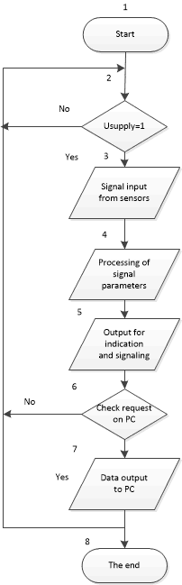
Figure 3 – Block – scheme of an algorithm for controlling the drying process of bulk solids in a drying drum oven
The operation of the block diagram takes place in the following order:
– in block 1 the power supply voltage is applied to the control unit and the unit starts its operation;
– in blocks 3 and 4 all sensors of technological parameters are polled, technological information received from them is input into the microcontroller, and it is processed. Interrogation of sensors and transducers from such physical quantities as pressure, gas, air, temperature, vacuum etc. takes place. Processing from sensors to transmitters takes place in form of conversion of specific physical quantity into electronic unified signal, which is further distributed to control units, indicating instruments, control registering devices and so on.
– in block 5 there is a visualisation of the received technological information. All signals and process data are displayed on the recording controllers as well as on the signalling units. In the event of a problem or malfunction, an audible or visual alarm is triggered and the signal is subsequently sent to a higher level of the control system;
– in units 6 and 7, the request from the host computer (higher level of the control system) is checked and the data are output via external communication channels to the host control computer. If the values received correspond to the set values, operation continues. If the values do not correspond to the set points, the supply of a certain physical quantity to the process object in the form of pressure, gas or air must be reduced or increased. If the values received during operation exceed the setpoints, the valve from the pipeline will be closed or adjusted to reduce the supply of the desired physical quantity.
Figure 4 shows a block scheme of a natural gas flow control algorithm for a drying drum oven.
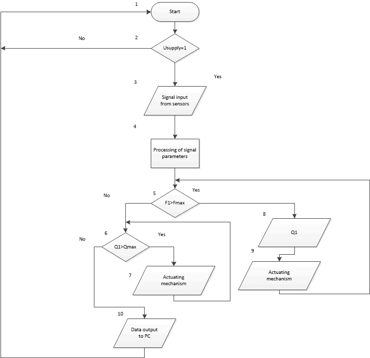
Figure 4 – Block – scheme of the natural gas and air flow control algorithm for a drying drum oven
The control process is as follows:
– units 1 – 2 – commissioning of the unit;
– block 3 – 4 – receiving and processing current information from sensors of technological parameters;
– block 5 – comparison of current gas and air flow rates with the upper level setpoint;
– blocks 6 – 7 are required for generation of external control signals to actuator (gaseous fuel actuator) for reduction of fuel consumption;
– blocks 8 – 9 are necessary to maintain the original fuel consumption Q;
– block 10 is required for outputting data obtained to a host computer (PC) about the progress of execution.
Fig. 5 shows the functional scheme of the automation of a drying drum oven
.
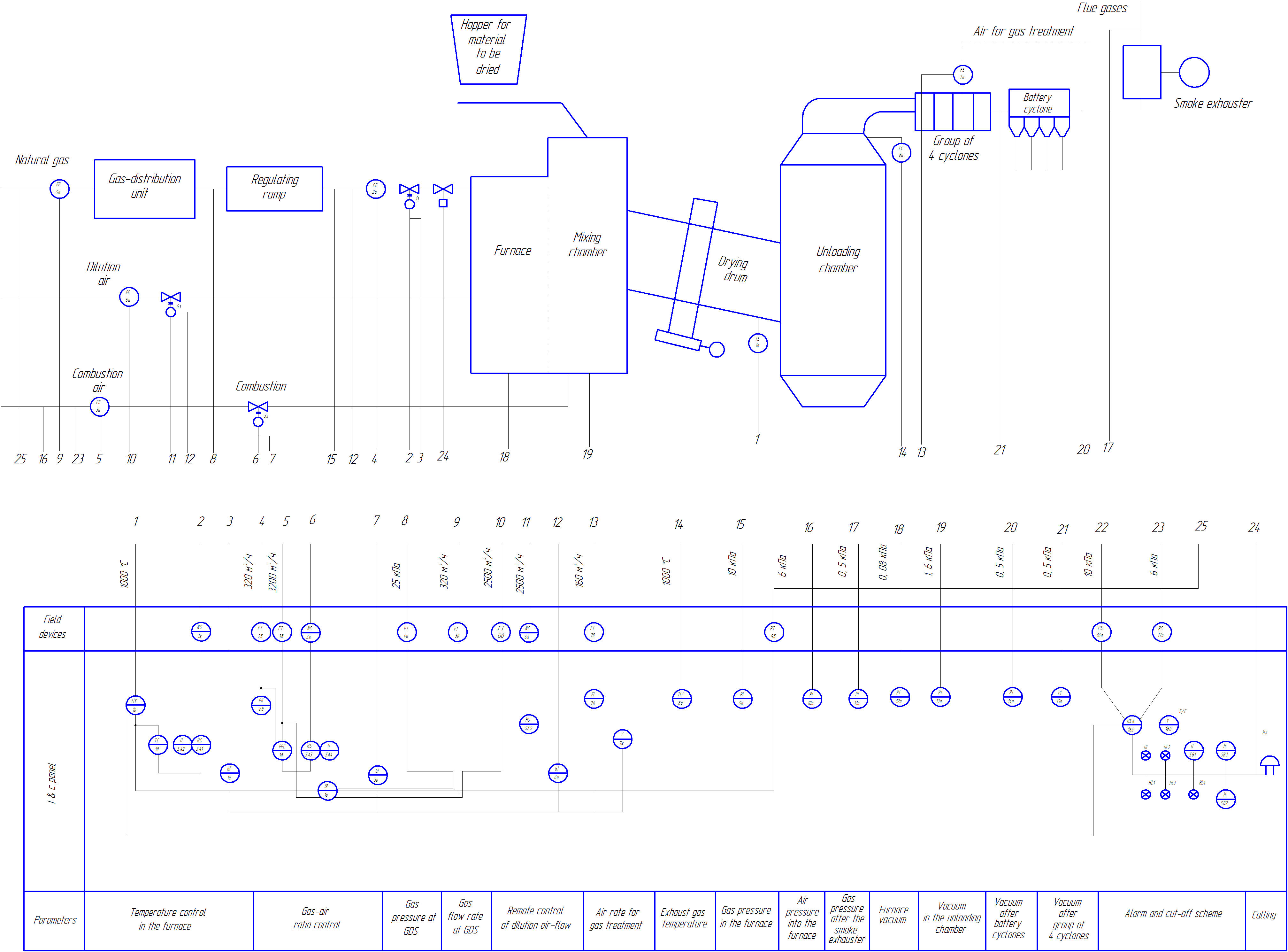
Figure 5 – Functional scheme of the automation of a drying drum oven
The process parameters of the drying drum oven are controlled as follows:
- Temperature control in the oven. The thermoelectric transducer TCA–2388 (item 1a) is installed on the drum oven and the output signal in the form of EMF is fed to the input of the measuring multilimetric transducer MTM–402–01–KA (K) (p. 1б). At this point, the thermo EMF is converted into a unified current signal. The signal is then transmitted to the MIK–51 control unit (p. 1д) and simultaneously the signal is transmitted to the 6–channel control recorder MTM RE–160–01 (p. 1o). The controller compares the set point with the current value and generates a control signal that goes to two switches UP5311 – 23 (SA1 p.) and UP5314 – C256 (SA2 p.), by means of which the regulation modes are selected. In the automatic mode the signal goes to the contactless reversing starter PBR–2M (p. 1ж) and switching electric one–turn mechanism МEО–63–25–6,3 (item 1з) which in its turn moves the regulating element mounted on a natural gas pipeline. The position of the regulator is monitored by a remote position indicator MTM – 103 (item 1и).
- Gas pressure monitoring after the GDS. The medium is measured between the gas distribution unit (GDS) and the regulating ramp. Upstream of the GDS, natural gas at high pressure flows and downstream of the GDS, natural gas at low pressure flows through the adjustment ramp. Then the measured parameter, that is pressure of 25 kPa, goes through measuring transducer
ELEMER – AIR – 10
(p. 4a), that converts received pressure in unified output current signal and sends it to electronic 6 – channel recorder MLM TE – 160 – 01 (p. 1o). The recorder itself displays all the necessary information about the state of the process parameter of the gas pressure after the GDS. - The gas flow rate at the GDS is monitored as follows. On the natural gas supply pipeline there is a standard chamber scheme DNB (p. 5a). From this diaphragm comes a pressure drop of 320 m3/ h to the measuring transducer
ELEMER – AIR–30
(p. 5б). The transducer outputs to one of the six channels of the measuring device MTM RE–160–01 (item 1o). - Remote control of dilution air flow. When air is supplied for dilution, the air itself enters the chamber standard DKS diaphragm (p. 6a). Then a pressure drop equal to 2500 m3/ h, is supplied to the measuring transducer
ELEMER – AIR – 30
(p. 6б). The unified current signal is fed to the recording device MTM RE – 160 – 01 (p. 1o). Using the switch UP5311 – 23 (p. SA5), switching to remote control is performed, as a result of which the signal is sent to the non–contact reversing starter PBR – 2M (p. 6g). The electric single–turn mechanism MEO – 63 – 25 – 6, 3 (p. 6h) is turned on, then it sends a signal to the remote position indicator MTM – 103 (p. 6i). - On the natural gas supply pipeline, the measured medium (pressure) enters the pressure transducer
ELEMER – AIR – 10
(p. 9б), which converts the received pressure into a unified current signal that enters one of the channels of the electronic recorderMTM RE – 160 – 01
(p. 1o). - When monitoring the discharge in the furnace, the discharge in the discharge chamber, the discharge after the battery cyclones and a group of 4 cyclones, a pressure gauge is required. Since all of the above parameters are measuring pressures, all of them will come to a pressure gauge such as the TNMP–100 membrane pressure gauge. (p. 11а, 12а, 13а, 14а, 15а).
Figure 6 shows a structural scheme of the automatic control of a drying drum oven.
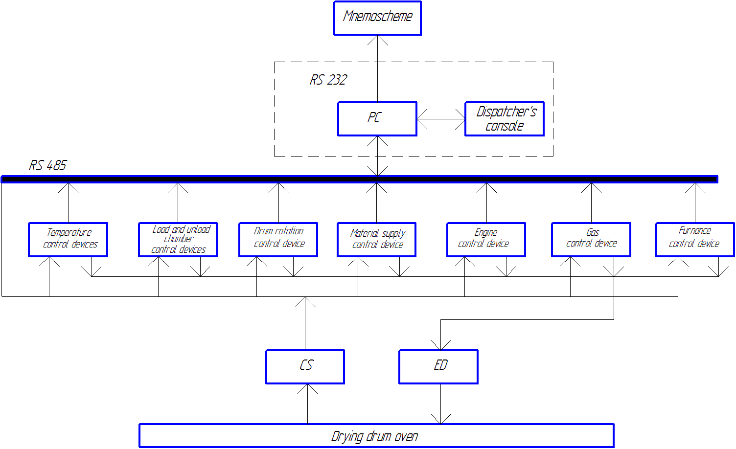
Figure 6 – Structural scheme of the control system for the process control system of the drying drum oven
In addition to the controlled object itself, the mimic diagram and the dispatcher's desk, the following symbols are present:
– CS – complex of sensors;
– PU – power unit with U = 12 V;
– ED – executive devices;
– CD – control devices;
– PC – personal computer.
Complex of sensors (CS) is necessary to control such technological parameters as temperature in the oven, gas–air ratio for combustion, gas pressure after GRP, air flow for dilution, vacuum and signaling. They are installed on natural gas and primary air pipelines, on fuel supply valves, etc.
Executive devices is necessary not only for не только for obtaining information from the measured values from the control object, but also for converting the obtained physical quantity into an electronic unified signal for further outputting it to indicating, recording and setting devices, in order to subsequently output the received signals through a EC and display them on the dispatcher's mnemonic diagram.
Variable differential pressure flowmeters with a constriction device in the form of a diaphragm of a chamber standard DCS will serve as sensors for measuring the flow.
Conclusions
The master's work is devoted to the actual scientific task is to increase the efficiency of the high–quality technological process of drying bulk materials in a drying drum oven by developing an automatic control system, as well as monitoring and regulating the main technological parameters of this control object. Within the framework of the research carried out:
- Analysis of the technological process of drying of bulk solids in a drying drum oven as an object of automation.
- A drying drum oven as an automatic control object is considered;
- Analysis of existing developments in drying drum oven automation;
- Justified directions for the automation of a drying drum oven;
- A control block scheme, an automation function scheme and process flow algorithms for the drying drum oven have been developed.
Further research is aimed at qualitative improvement of the proposed methods and developments to improve the technological process of drying of bulk materials in a drying drum oven.
When writing this abstract, the masters work has not yet been competed. Final competition: June 2023. The full text of the work and materials on the topic can be obtained from the author or his manager after that date.
References
- Глинков Г. М. АСУ ТП в черной металлургии: учебник для вузов. / Г. М. Глинков, В. А. Маковский – 2 – е изд., перераб. и доп. – М.: «Металлургия», 1999. – 310 с.
- Григорьева В. А., Зорина В. М. «Промышленная теплоэнергетика и теплотехника: Справочник». – М.: Энергоатомиздат, 1983. – 588 с.
- Громаков Е. И. Проектирование автоматизированных систем: учебно – методическое пособие. – Томск: Томский политехнический университет, 2010. – 173 с.
- Дубровский А. Х. Устройство электрической части систем автоматизации. – М.: Энергоатомиздат, 1984. – 264 с.
- Котов К. И., Шершевер М. А. Средства измерения, контроля и автоматизации технологических процессов. – М.: Металлургия, 1987. – 496 с.
- Михеев А. А. Методы и средства автоматизированного управления сушильной камерой (промышленность): дисс…. канд. техн. наук: 05. 13. 06/ Михеев Алексей Александрович. – Ируктск, 2015. – 133 с.
- Плетнев Г. П. Автоматическое регулирование и защита теплоэнергетических установок. – М.: Энергия, 1976
- Сергиенко А. Б. Цифровая обработка сигналов. – Спб.: Санкт – Петербург, 2002.
- Уэйкерли Д. Проектирование цифровых устройств / Д. Уэйкерли. – М.: Постмаркет, 2002. – Том 2. – 528 с.
- Михайлов Ю. Ю., Лабутин В. А., Быков И. Н., А.Ю. Михайлов. Моделирование процесса сушки в барабанной сушилке с учетом влияния продольного перемешивания сушильного агента. – Владимир: Владимирский государственный университет, 2010. – 3 с.
- Гартман Т. Н., Клушин Д. В. Основы компьютерного моделирования химико – технологических процессов: учеб. пособие для вузов. – М.: Академкнига, 2006.
- Питухин Е. А. Математическая модель управления качеством работы сушильной установки барабанного типа/// Труды Петрозаводского государственного университета. Вып. 6. 1997
- Кашьян Р. Л. Построение динамических стохастических моделей по экспериментальным данным. – М.: Наука, 1983.
- Vasiltsov I. Evolutionary technique to elementary coding of the internal states of the state machine / I. Vasiltsov // Proceedings of the 2002 NASA/DoD Conference on Evolvable Hardware. – 2002. – pp. 63–64.
- Шувалова Л.А. Структура программного комплекса синтеза и верификации моделей цифровых автоматов / Л.А. Шувалова, Д.Н. Моамар, Т.Ю. Уткина // Системи обробки інформації. – Харьков, 2010. – № 5. – С. 149–152.