
Abstract
Content
- Introduction
- 1. Relevance of the topic
- 2. Purpose, functions and tasks of the ACS
- 3. Design and technological features of an oxygen turbocompressor
- 4. Overview of the automatic turbocharger control system
- 4.1 Formalization of the control object
- 4.2 Analysis of the block diagram of the ACS of the turbocharger
- Conclusion
- References
Introduction
The efficiency and durability of the complex as a whole depend on the efficiency and reliability of the compressor unit.
Basically, centrifugal compressor units are an integral part of most industrial and public complexes, they are used at compressor stations of metallurgical plants, machine-building enterprises, in the mining, oil refining industries, for transporting large volumes of gas.
Turbochargers are quite durable, reliable and environmentally friendly units that meet modern technological requirements and established standards
Pressure control in the oxygen compressor is a priority task when creating automatic control systems for a turbocharger, since the degree of oxygen compression and its supply to factory facilities and installations completely depends on the compressor performance, which, when creating an effective ACS, can be adjusted in accordance with the user's requirements for the developed system.
The main issue in the automation of the compressor is to ensure the uninterrupted supply of compressed oxygen to the factory network, of the required quality and quantity.
1. Relevance of the topic
The relevance of this topic is determined, firstly, by the fact that providing compressed gas equipment, installations and furnaces in the metallurgical industry is a paramount task. Secondly, in modern conditions, compressor units as a whole determine the efficiency of the oxygen compressor shop at the enterprise. The problem of creating an efficient and cost–effective automatic control system for a compressor unit at a metallurgical enterprise is still an urgent task.
2. Design and technological features of an oxygen turbocompressor
Oxygen turbocompressors are reliable machines and significantly outperform reciprocating oxygen compressors in terms of performance. Another important advantage is that the oxygen compressed in turbochargers is not contaminated with water or emulsion.
Compressors are divided by the number of compression stages into:
– single–stage compressors;
– two–stage compressors;
– multistage compressors.
A multistage centrifugal turbocharger KTK 12.5/16 was chosen as the object under consideration.
The compressor is designed to compress and supply gaseous oxygen to the plant's consumer network. The working agent is oxygen with a concentration of up to 99.8% by volume with relative humidity under suction conditions up to 100% [2].
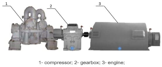
Figure 2.1 – External view of the oxygen turbocharger
An oxygen turbocharger (Fig. 2.1) consists of the following main components: compressor (1), housing, rotor (2), synchronous motor (3), bearings and refrigerators. The compressor rotor consists of a steel shaft, on which the impellers and the unloading piston (dummis) are seated.
(Fig. 2.2) shows a generalized diagram of a multi-stage centrifugal turbocharger. To ensure the highest degree of oxygen compression, the use of a multi–stage turbocharger will allow, which prevails over the use of single–stage compressors, due to the achievement of high pressure indicators.

Figure 2.2 – Generalized diagram of a multistage compressor
(animation: 6 frames, 145 kilobytes)
Considering the generalized structure of the compressor, it can be seen that structurally it consists of: a working shaft (1), a suction pipe (2), an outlet pipe (3), a compressor housing (4), impellers (8).
The compressor has 8 compression stages distributed as follows:
– the first building (5) – 2 steps;
– the second building (6) – 4 steps;
– the third building (7) – 2 steps
The process of oxygen compression in a turbocompressor installation is polytropic, i.e. in the process of gas compression, it is heated, due to the transition of oxygen into heat, the energy expended to overcome friction forces.
3. Purpose, functions and tasks of the ACS
The purpose of the system being created is to improve the system for ensuring the uninterrupted supply of compressed oxygen to factory facilities and installations by creating an automatic pressure control system for the turbocharger.
To achieve this goal, it is necessary:
– have information about the value of pressure after the bypass;
– have information about the pressure value at the compressor outlet;
– to implement algorithms for calculating the control signal based on all available information;
– to implement the connection of the received system with the control room.
The main task of regulating the operation of compressor units and stations is to maintain a constant predetermined pressure of compressed air in the pneumatic network by changing the performance of the compressors in accordance with the consumption of compressed oxygen.
As a result, it is obvious that the total energy costs at automated oxygen stations will be lower than at stations where there is no automation.
The main functions that an automatic control system should perform:
1) control functions:
– normalization of oxygen pressure at the outlet of the turbocharger;
2) information functions:
– collection of information from sensors and transmission to the control controller;
– signaling of emergencies;
– communication of the control controller with the control room for receiving and transmitting data.
The main function of using the frequency control of the engine speed is to maintain the pressure value at the compressor outlet by automatically controlling the flow rate by reducing or increasing the engine speed, which provides the required value of oxygen compression to the factory network [5].
The use of a frequency drive will provide:
– maintenance of a given pressure level;
– smooth change in oxygen consumption;
– rejection of additional shut–off and control valves;
– high performance of the turbocharger in the minimum load mode;
– increase the value of the time between failures in the turbocharger installation;
– reducing the likelihood of surge during compressor operation;
– reduction of the number of starting currents in the electrical network of the turbocharger.
4. Overview of the automatic turbocharger control system
The development of an automatic control system for a turbocharger, in turn, involves the control and management of parameters that affect the operating modes of the control object.
To ensure effective control of the compressor unit, it is necessary:
– measure the pressure at the compressor outlet;
– measure the consumption of oxygen;
– regulate the engine speed using a high-voltage frequency converter (FC) to maintain the set pressure value at the compressor outlet.
4.1 Formalization of the control object
To ensure the normal operation and timely detection of violations in the operation of an oxygen turbocompressor, it is necessary to constantly monitor a number of parameters, analyze the situation, issue control actions and alarms in case of deviation of the controlled parameters.
As a result of the above, it is necessary to highlight the control and regulation of pressure and flow, which are key parameters for the full operation of the compressor.
Successful regulation of the pressure at the compressor outlet requires high speed of the automatic control system and low inertia of the system [9].
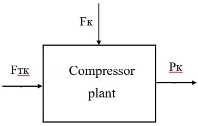
Figure 4.1 – Oxygen turbocharger as a control object
Based on the foregoing, controlled variables, control and perturbing actions are determined (Fig. 1) [1].
Successful pressure control at the compressor outlet requires high speed of the automatic control system (ACCS) and low inertia of the system. The phenomenon of surge should also be taken into account, which must be compensated for in order to prevent the object from degrading the output characteristics or taking it out of service.
The adjustable parameter is:
– oxygen pressure at the compressor outlet PK, MPa.
The control parameter is:
– performance of the turbocharger FTK, m3/s.
The perturbing parameter is:
– consumption FK.
4.2 Analysis of the block diagram of the ACS of the turbocharger
The principle of constructing an ACS by deviation (feedback principle) using one main control loop for a given object – an oxygen turbocompressor does not allow obtaining the required control efficiency, since the main perturbation in the consumed oxygen consumption will remain unaccounted for, without which it will be impossible to accurately control the constantly changing pressure value at the compressor outlet by changing the compressor capacity. In turn, the application of the combined control principle provides for the simultaneous use of deviation control and disturbance control, combining the advantages of the two control principles in one system [3].
The combined automatic control system for an oxygen turbocompressor is a combination of a control object, a regulator and a sensor, and the regulation is carried out according to the controlled variable and according to the main disturbing effect (Fig. 2).
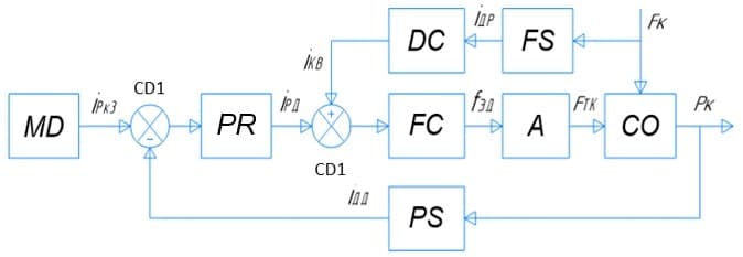
Figure 4.2 – Combined control principle
Functional elements of the system: CO – control object (oxygen turbocompressor); MD – master device; PS – pressure sensor; FS &ndash flow sensor; CD1, CD2 – comparing devices; PR – pressure regulator; FC – high&ndashvoltage frequency converter; A – actuator (turbocharger engine).
The principle of operation of the ACS by an oxygen turbocompressor using the combined control principle is as follows: the pressure is measured by a sensor (PS), controlled by the variable PK, the current signal IPS, using a comparing device (CD1) is compared with the current setting signal IPK3. The comparison element generates a mismatch signal, which is fed to the regulator (PR), where the control action IPR is formed using the pressure regulator (PR). With the help of a flow sensor (FS), the main disturbance is measured - the consumed flow (FК) and the signal is fed to the disturbance compensator (DC), which generates an error signal (IDC) of a changing disturbance and enters the comparator (CD2), which compares the signal with IPR and, taking into account the changing disturbance, forms a common control action IFC for the frequency converter (FC ), which, in turn, generates and issues a control action in the form of the required change in the frequency of the supply voltage (fDM) to the actuator (A), for the required change in the speed of its shaft, with the help of which the performance is controlled of the entire control object (CO), a change in the performance of the turbocharger leads to a corresponding change in the oxygen pressure PК at the outlet of the compressor unit.
Based on the analysis of the features of an oxygen turbocompressor as an object of automatic control and the concept of building an automatic control system proposed above (Fig. 2), a block diagram of an oxygen pressure automatic control system for an oxygen turbocompressor was developed, which is shown in Fig. 3 [1].
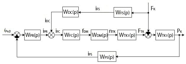
Figure 3.1 – Structural diagram of the oxygen turbocompressor pressure control system
According to the block diagram obtained (Fig. 3), the automatic pressure control system of the oxygen turbocompressor consists of the following elements: WTK1(p) and WTK2(p) &ndash transfer functions of the turbocompressor; WDM (p) is the transfer function of the oxygen turbocompressor drive motor; WFC(p) is the transfer function of the frequency converter; WPR(p) is the transfer function of the pressure regulator; WDC(p) is the transfer function of the perturbation compensator; WFS(p), WPS(p) – transfer function of oxygen flow sensor and pressure sensor.
The developed ACS is implemented using a combined control principle: with feedback on the controlled variable – the oxygen pressure at the outlet of the turbocharger PK and a compensation channel on the main disturbance – the oxygen consumption FK (Fig. 3).
In the ACS being developed, the controlled variable is the oxygen pressure at the outlet of the PK turbocharger, measured by the pressure sensor WPS(p), is converted into the corresponding direct current electrical signal iPS. The output signal of the pressure sensor iPS is compared with the current signal iРкЗ, which is the master action in the ACS and the value of which is determined by the required value of the oxygen pressure at the compressor outlet РКЗ = 1.6 MPa (Fig. 3). The discrepancy signal is fed to the pressure regulator WPR(p), which forms the control action iPR.
The compensation channel for the perturbation – the consumed oxygen consumption FК includes an oxygen consumption sensor WFS(p) and a perturbation compensator WDC(p) (Fig. 3). This channel makes it possible to take into account in the general control action iFC the influence of a changing disturbing action – the consumed oxygen consumption by adding the signal of the disturbance compensator iDC to the total control action iFC (Fig. 3).
The general control action iFC is fed to the actuator, the functions of which in the developed ACS are performed by the frequency converter WFC (p), which generates and outputs the control action in the form of the required change in the frequency of the supply voltage fDM to the turbocharger drive motor WDM(p) for the required change in its rotational speed shaft nTK. As a result, the rotational speed of the turbocharger shaft nTK changes and, accordingly, the performance FTK of the oxygen turbocompressor. A change in the performance of the turbocharger leads to a corresponding change in the oxygen pressure PK at the outlet of the turbocharger (Fig. 3) [11].
Conclusion
An analysis of the design and technological features of the object made it possible to review the automatic control system built according to the combined principle, which will allow the generation of a control signal, using feedback on the controlled variable – PK, and also taking into account the compensation of the perturbation for the oxygen consumption – FK, due to the oxygen pressure at the compressor outlet will be maintained at a predetermined level, ensuring an uninterrupted supply of compressed oxygen to factory facilities and installations.
References
- Гаврилов П.Д., Гимельшейн Л.Я., Медведев А.Е. Автоматизация производственных процессов. Учебник для ВУЗов. М.: Недра, 1985, 215с.
- Частотное регулирование производительности компрессоров. НТЦ ЭНЕРГО–РЕСУРС [Электронный ресурс] URL:
https://en-res.ru/stati/chastotnoe-regulirovanie-proizvoditelnosti-kompressorov.html.
- Миллер Р. Теория переключательных схем / Р. Миллер. – М.: Наука, 1971. – Том 2: Последовательностные схемы и машины. – 304 с.
- С.А. Абдурашитов, А.А. Тупиченков, И. М. Вершинин, С.М. Тененгольц. Насосы и компрессоры. М.,
Недра
, 1974. 296 с. - Михайлов А.К., Ворошилов В.П. М69. Компрессорные машины: Учебник для вузов. – М. Энергоатомиздат, 1989. 288 с.
- В.И. Елин, К.Н. Солдатов, С.М. Соколовский. Насосы и компрессоры 1958. 353 с.
- Бухарин Н.Н. Моделирование характеристик винтовых компрессоров. – Л.: Машиностроение, 1983. – 214 с.
- Гликман Б. Ф. Математические модели пневмогидравлических систем. – М.: Наука. Гл. ред. физ.– мат., 1986. – 368 с.
- Башарин А.В., Новиков В.А., Соколовский Г.Г. Управление электроприводами: Учебное пособие для вузов. Л.: Энергоиздат. Ленинградское отделение, 1982. – 392 с.
- Важнов А.И. Переходные процессы в машинах переменного тока. Л.: Энергия. Лениградское отделение, 1980. – 256 с.
- Лукас, В.А. Теория автоматического управления. / В.А. Лукас – М.: Недра, 1990. – 416 с.