
Abstract
Contents
- Introduction
- 1. Theme urgency
- 2. Goal and tasks of the research, planned results
- 3. Review of research and development
- 4. Main part
- Conclusion
- References
Introduction
Vibrating machines were first used in industry at the end of the 19th century.
A vibrating feeder is a device for uniform and controlled supply of bulk materials, as well as piece goods, from loading devices further along the production line to transporting or technological units. Dual-mass vibrating feeders consist of a load-carrying body, a vibration motor, working elastic links, shock absorbers, as well as a reactive mass, which is a heavy installation frame or the vibrator itself. However, there are a number of disadvantages, among which vibration, which is transmitted to the foundation, deserves special attention. This dynamic load on the foundation and components of the vibrating machine itself reduces the durability of the installation as a whole.
1. Theme urgency
The relevance of the work is due to the fact that constant vibration destroys the foundation of the installation.
By reducing the destructive effects of vibration, you can extend the life of the vibrating feeder itself and avoid downtime in production. It is also worth noting that the service life of vehicles located together with it in the conveyor line, as well as their safety, largely depends on the efficiency of the feeder.
Many scientists around the world are conducting experiments and putting forward their proposals to improve the design of the vibrating feeder to this day. It follows that the problem is relevant.
2. Goal and tasks of the research, planned results
The main goal of this work is to develop a vibrating feeder with optimal parameters, analyze the design, and search for options for reducing additional dynamic loads on the suspension and foundation.
Tasks to achieve this goal:
- Review the status of the issue;
- Create a mathematical model of a vibratory feeder;
- Perform an analysis of the model, determine the feasibility of using the designed vibrating feeder;
- Create a mathematical model of cargo movement;
- Calculate the required rigidity of the elastic connections (suspension).
3. Review of research and development
A large number of works are devoted to issues related to design improvement. In order to increase productivity, reduce transmitted dynamic loads and increase reliability, scientists are still conducting research and offering their own modernization options.
Article [1] presents an analysis of vibrating feeders used in mining operations. Particular attention is paid to vibratory feeders with a working element of low bending rigidity. The results of laboratory and numerical experimental studies are presented, and it is concluded that the use of elastic support elements in the design of a vibrating feeder makes it possible to increase the intensity of vibrations of the loading area, thereby creating conditions for the effective supply of bulk and cohesive materials.
Design diagrams are presented that allow expanding the scope of application of existing vibrating feeders. The authors of the article [2] propose using additional elements (chains, ropes) to move difficult-to-transport materials (cohesive, sticky, hot) through the feeder. It is noted that all presented schemes can be structurally combined in any necessary combination.
In [3], the authors paid attention to a device for preventing leakage of bulk material when the vibrating feeder is turned off. It is proposed to use a leaf or rotary valve; both options do not greatly complicate the design and do not require any additional actions.
The authors proposed a vibrating feeder [4], the design of which provides for the division of the supplied mass into 3 flows, each of which has 3 times less intensity than the intensity of the total flow. It is noted that application is possible in construction, chemical and any other industry where it is necessary to supply small-sized and bulk materials and separate the flows during feeding.
In article [5], the author draws readers’ attention to the fact that an increase in the depth of mining operations in quarries leads to an increase in the volume of transported overburden. At the same time, the use of heavy-duty dump trucks on lower horizons is difficult, and sometimes even impossible, due to the size of the working platforms and the need to overcome large slopes. This implies the need to use combined transport. The author suggests using bunker transfer points with vibration release of rock mass, noting that the use of two vibration exciters can increase productivity up to 2 times.
In article [6], the author talks about his experimental study of the operation of a prototype vibrating feeder on a combined parametric resonance. A significant reduction in parasitic oscillations has been proven, and the threshold for excitation of resonant parametric oscillations has been determined. It is noted that the use of this type of vibrator provides high stability and reduced energy costs.
A two-section vibrating feeder is proposed, which makes it possible to cool and additionally clean heat-treated cullet from lightweight impurities. Area of application: glass industry and municipal solid waste processing enterprises. The author also notes the compact design of such a feeder [7, 8].
Paper [9] presents scientific and practical results of improving vibrating screen feeders for the mining and metallurgical industry based on materials from the dynamic calculation of a vibrating screen feeder with two multidirectional self-balanced vibrators. The author notes that the proposed design will increase screening efficiency by 15-20 percent and improve the self-cleaning of the screen.
Article [10] presents the main scientific and practical results of research, dynamic calculation and improvement of a small-sized vibrating feeder for underground mining. The author recommends a small-sized PVG to reduce the cost of work and increase the productivity of the feeder by 3.5-5 times compared to scraper delivery of rock mass.
An analytical method is presented for calculating the movement parameters of an arbitrary point of the oscillating part of the distribution grid mill of an installation for introducing preservatives into feed grain. The author of the article [11] notes that the results of the work can be used to simulate various conditions for the dosing process and distribution of bulk material on the surface of the working body of a vibrating feeder.
The author of the article [12] notes that despite the simplicity of their design, “classical” screens have low efficiency (low screening efficiency), require a significant screening surface area and have significant height dimensions. In the proposed version, the design of the sifting surface has been improved and the movement of particles has been modernized (giving the sieving surface free and forced oscillations of different amplitudes), which makes it possible to increase the efficiency of the system without increasing its overall dimensions.
Work [13] discusses the technological features of cleaning container glass cullet from paper labels. The design features of vibrating feeders with the ability to remove lightweight impurities during material feeding are described.
The author of the article describes the advantages of using a vibrating feeder-doser in production in order to eliminate feed unevenness. By using a vibrating feeder, you can not only achieve uniform feeding of the material, but also regulate the feeding intensity [14].
The design of a vibrating feeder is described. The main components are indicated, the movement of the material during feeding is described. It is concluded that although modern vibratory feeders have quite good technical and operational qualities, the development of feeders with increased productivity and maintainability is an urgent task [15].
Work [16] is devoted to the study of vibrational movement of a layer of bulk material in vibrating feeders and the development of a mathematical model of their electromagnetic drive. The resonant frequency of vertical and longitudinal vibrations of the vibrating feeder tray has been determined. Thanks to the mathematical model, it is possible to determine the required power and select the type of electric drive from the point of view of equipment energy efficiency.
Article [17] presents an analysis of the technical means used to improve the safety of work during the formation of dump trucks. The authors of the article propose the use of a vibrating spoiler to improve work safety and eliminate the loss of human resources and expensive equipment in the event of landslides.
Reloading systems have a significant impact on the cost of mining. The use of bunkers instead of combined transport increases the efficiency of the reloading system. The authors of the article [18] note that the most effective is the use of a bunker in the form of an “inverted obelisk” with a vibrating screen feeder.
The work [19] describes the design, advantages, and nuances of possible schemes for using vibrating feeders. The author writes that vibrating conveying machines are widely used to move bulk cargo in various sectors of the national economy and suggests various possible ways of using feeders as, for example, vibrating mixers to obtain a bulk mixture of high homogeneity at low unit costs.
The article [20] presents the results of numerical and physical modeling of the dynamics of a vibrating feeder. The degree of influence of the design parameters of elastic support elements on the amplitude of vibration of the working element is determined. A rational ratio of the sizes of elastic support elements has been established. It has been established that the design parameters of the supporting elements mainly affect the amplitude of the longitudinal vibrations of the loading section of the working body.
Article [21] presents the results of studies of the process of vibration movement of bulk materials, which served as the basis for the creation of vibration equipment for the mining industry. An analysis of the capabilities and technical characteristics of the machines being created is carried out in comparison with existing equipment, similar in principle of operation and purpose, and their advantages are shown. The vibrating feeder of the proposed design is capable of uniformly releasing bulk materials, and the use of a spreader allows increasing the safety of mining operations and obtaining a significant economic effect.
The authors describe the design features of a vibrating feeder with an elastic working body, as well as its advantage compared to a feeder of a classical design. The dynamics of the working body during operation of two vibration exciters in synchronous and beating modes was studied by modeling. In the course of the work, the conditions for stability and restrictions on the use of the first and second modes were determined. The authors emphasize that the possibility of implementing various modes of vibration transportation allows one to expand the scope of application of vibratory feeders with an elastic working body, and the possibility of replacing one powerful vibration motor with several motors of lower power allows one to increase the length of the line [22].
The article [23] analyzed machines for transporting bulk cargo. Their advantages and disadvantages are given. It has been established that a vibrating feeder can be used to transport bulk materials, the advantages of which are simplicity of design, low wear of the load-carrying body, low energy consumption, and ease of maintenance.
Work [24] is devoted to the study of costs in vibratory transport machines. It is noted that energy costs should be divided into necessary and avoidable. And if nothing can be done with the necessary costs, then avoidable costs should be sought to be minimized. For example, avoidable energy costs include those required when starting a machine. The paper discusses possible ways to reduce or eliminate startup costs.
The article [25] discusses vibrations in the drive of vibrating machines with an inertial vibration exciter, in which the electric motor shaft is connected to the exciter shaft through elastic couplings, V-belt drives, and cardan shafts. Such a connection is necessary for a number of vibration machines in which the vibration motor is located on a stationary base, and the vibration exciter shaft is located on the vibrating part of the machine body. It has been proven that the presence of the specified shaft connection introduces features into the dynamics of the vibrator drive. To prevent the occurrence of dangerous vibrations during operation or during start-up, these features should be taken into account at the design stage.
The article [26] describes the disadvantages of the classical design when working with fine bulk materials. The authors propose a special design using a chute with sections that are set at a certain height and are designed to ensure normal gas permeability, which will allow the movement of fine materials without loss of productivity and uneven movement.
In [27], the design features of a disk vibrating feeder were analyzed. Research was carried out and research results were presented. Technical solutions have been identified to ensure a reduction in specific energy consumption during the operation of a disk vibrating feeder.
The author noted the widespread use and application of disc vibrating feeders. The structure of this type of feeder is described, the advantages are noted, and emphasis is placed on the reliability and simplicity of the design. The research was aimed at finding technical solutions to reduce the energy consumption of a disk vibrating feeder [28].
Scientific articles [29, 30] discuss the results of increasing the reliability and efficiency of vibrating grate feeders and analyze the operation of various designs. In order to increase the efficiency and wear resistance of the working surface, a design with improved grate bars was proposed. It has been proven that the presence of curved projections on the working surface of the grate helps to increase screening efficiency by 25 percent.
The problems of transporting bulk cargo using conveyor systems are described. The possibility of using vibrating feeders to transfer material from one conveyor to another is considered. The authors note the need for a more in-depth study of low- and high-frequency vibrations of conveyor belts [31].
In [32], the authors analyzed the design features of vibrating feeders for cohesive materials. A proprietary design has been proposed, a design diagram has been presented, and the relationship between the characteristics of the feeder working body and the parameters of the elastic support elements has been established.
Article [33] talks about the use of vibrating feeders in the agricultural sector. Application on a grain processing line is discussed. In the course of the work, the authors determined the energy parameters and concluded that it is advisable to use vibrating feeders in this area.
The authors note that the use of vibration installations requires optimization of their operating modes. Since rubber-metal products are used in the form of elastic elements, which are characterized by the nonlinearity of their damping properties, the question arises of a more in-depth description of the properties of rubber as a shock-absorbing material with the further goal of optimizing the ongoing processes. In the course of the work, a methodology for calculating damping characteristics and dependencies was determined. It was noted that rubber-metal blocks manufactured taking into account the above will eliminate the possibility of limiting productivity and increase the durability of the feeder suspension [34].
The work [35] analyzed the invention, which relates to a production line for processing aluminum slag. The structure of the line and the design features of the machines installed on the line are described. The dust and gas purification device is designed to ensure reliability and improve the environmental situation at the enterprise; its design is described.
Article [36] talks about increasing the efficiency of vibration systems. The author studied the processes occurring during the operation of a vibrating feeder and proposed the use of rotary inertial vibration drives. Based on the research conducted, after using vibrating drives of this type, there is a significant increase in the efficiency of vibrating feeders.
The article [37] noted the high degree of distribution of vibrating feeders on lines associated with the movement of rock masses. Having developed a mathematical model, the authors were able to obtain the dependence of the moment of resistance of the vibration machine on its angular velocity. It is noted that the application of the obtained data in practice can have a positive effect on the technical and economic performance of the machine and increase the reliability of the equipment.
Work [38] is devoted to the study of a pneumatic vibration exciter. The design of an exciter of this design, as well as its operating principle, is described. As a result of the research, the author notes that the use of pneumatic vibration exciters will simplify the design and reduce shock loads in the drive.
In [39], the author describes a hydrodynamic vibration exciter for a vibrating feeder and other machines that operate due to vibration. The design and operating principle of a hydrodynamic vibration exciter is described. The author notes that it is important to observe the parameters of the vibrator, the ratio of linear dimensions and mass. A variant of a vibration machine with this type of vibration exciter is proposed.
The vibration sensor is designed for remote monitoring of the operation of vibrating feeders. The work [40] describes its structure, design features and operating principle. The purpose of upgrading the sensor design is to expand the scope of its application.
4. Main part
The work used calculation methods APM FEM KOMPAS 3D, as well as a load application simulator of the SolidWorks program. To carry out the calculations, the design of a vibrating feeder was developed and modeled, the general view of which is shown in Fig. 1.
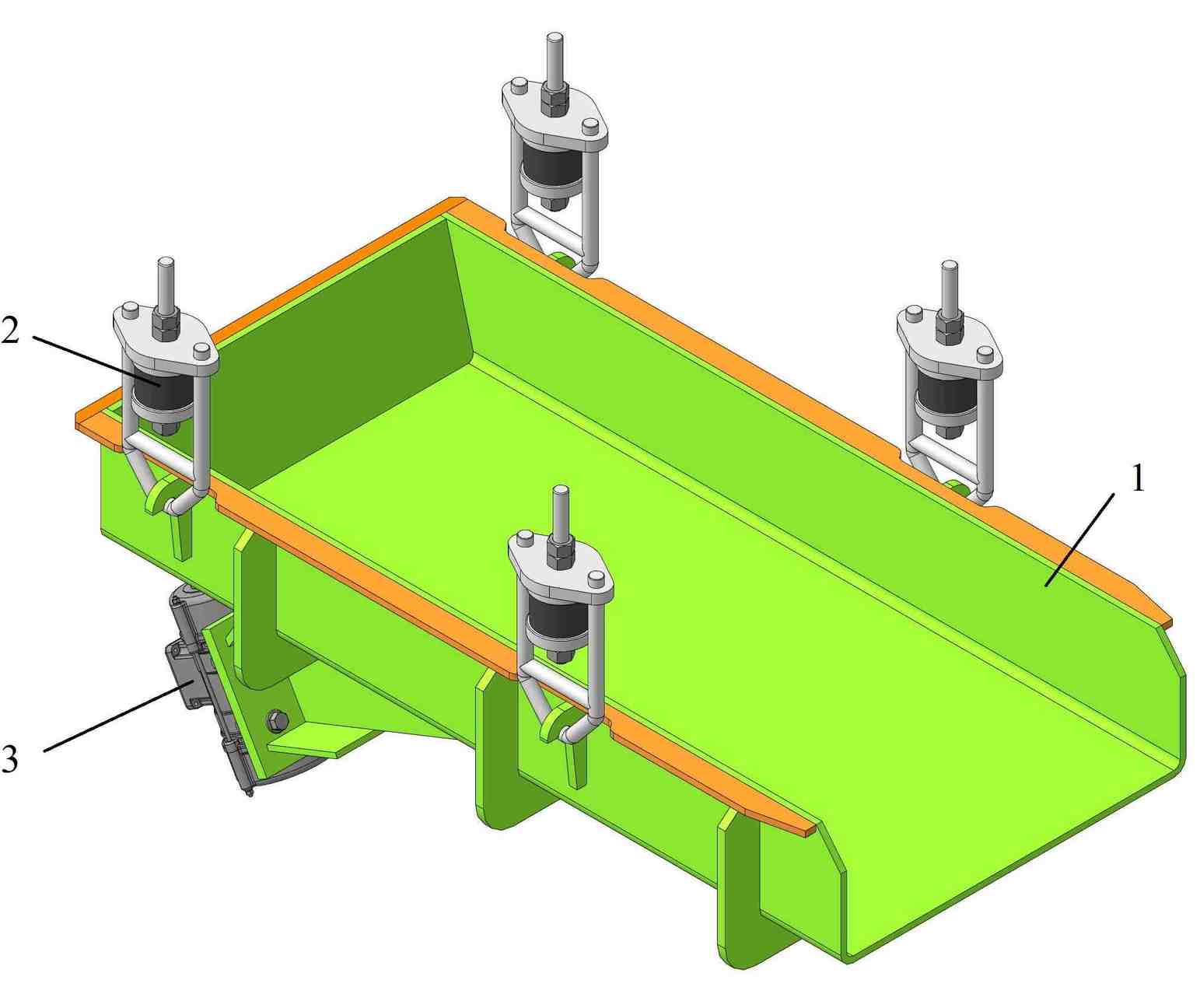
Figure 1 – General view of the vibrating feeder: 1 – frame; 2 - suspension; 3 - drive
Structurally, the vibrating feeder consists of a frame, hangers and a drive. The frame is a welded structure that includes a groove with a platform for mounting the drive. To ensure strength, the gutter has ribs and is attached to the hangers using hooks. The suspension makes it possible to reduce vibrations and dynamic loads that arise during operation of the drive, performing the function of a vibration damper. The design of the suspension is shown in Fig. 2
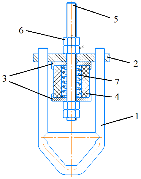
Figure 2 – Vibrating feeder suspension: 1 – bracket; 2 - flange; 3 – damper covers; 4 - damper; 5 – hairpin; 6 – nut (4 pcs.); 7 - spring
The drive is a vibration exciter consisting of an electric motor, on the axis of which a load with an eccentric in the form of an unbalance is placed. In order for a directed driving force to appear, it is necessary to use two vibration exciters rotating synchronously towards each other. Self-synchronization is achieved due to the proximity of vibration exciters to each other and a common rigid base. As shown in Fig. 3, when the drive is operating, both driving forces will act in the same direction, creating vertical vibrations, and in the “horizontal” position of the unbalances, the resulting driving force of one vibration motor will be extinguished by the driving force of the second, and accordingly, unwanted horizontal vibrations will be avoided.
Figure 3 – Animation of the positions of the unbalances during the operation of vibration exciters. Number of frames - 8
The calculations show that the maximum volume of cargo on the chute is no more than 0.32 m3. Consequently, with a bulk density of the transported material equal to 3.3 t/m3, the mass of the cargo does not exceed 1.1 t. Using the APM FEM KOMPAS 3D application, loads were simulated and places of increased stress were identified (Fig. 4a), as well as the values of safety factors strength (Fig. 4b).
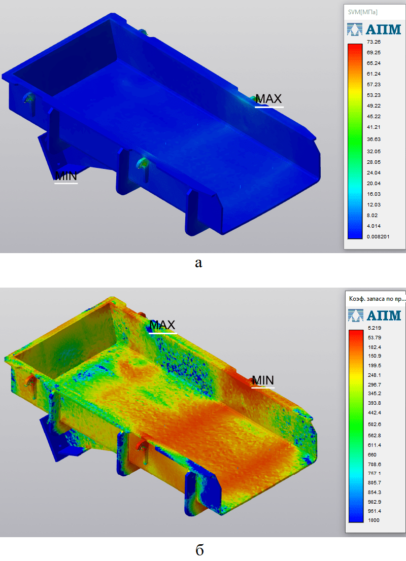
Figure 4 – Results of modeling the loading of the vibrating feeder trough: a – stress distribution; b - safety factor values
Using the proposed model, calculations were carried out for various combinations of parameters and geometric dimensions. From Fig. 4a it follows that the maximum stresses in the vibrating feeder structure are located in the area of the suspension hooks and amount to 73.3 MPa. The tensile strength of the steel used is 580 MPa, so the stresses do not go beyond the permissible limits. As shown in Fig. 4b, the minimum safety factor is 5.2. For vibrating machines, the safety factor, taking into account the dynamic coefficient (1.7 under shock and sudden loads, significant fluctuations), can be equal to 4.2. The analysis confirmed the strength of the structure and showed that the thickness of the metal used needs to be reduced - the gutter wall from 12mm to 8-10mm; stiffening ribs from 10mm to 6-8mm. By changing the thickness of the metal used, we will reduce the weight of the machine without losing the strength of its structure. It is also necessary to increase the width of the suspension hooks, because they are stress concentrators, from 16mm to 22-26mm in order to distribute local loads.
Conclusion
To reduce metal consumption, it is necessary to reduce the thickness of the metal used in the design of the vibrating feeder by 1.5 times, and make the hooks wider to increase the area of contact with the suspension, in order to distribute local loads.
At the time of writing this abstract, the master's thesis has not yet been completed. Completion of work will be in May 2024. The full text of the work and materials on the topic can be obtained from the author or his supervisor after the specified date.
References
- Левенсон, С. Я. Использование вибрационных питателей в современных технологиях добычи и переработки геоматериалов / С. Я. Левенсон, Л. И. Гендлина, Е. Г. Куликова // Фундаментальные и прикладные вопросы горных наук. – 2017. – Т. 4, № 1. – С. 28-33.
- Левенсон, С. Я. Обоснование новых конструктивных схем вибрационных питателей для выпуска геоматериалов из накопительных емкостей / С. Я. Левенсон, Л. И. Гендлина, Е. Г. Куликова // Фундаментальные и прикладные вопросы горных наук. – 2018. – Т. 5, № 1. – С. 258-263.
- Левенсон, С. Я. О расширении возможности использования вибрационных питателей при выпуске сыпучих материалов из накопительной емкости / С. Я. Левенсон, Л. И. Гендлина, Е. Г. Куликова // Политранспортные системы : Материалы X Международной научно-технической конференции, Новосибирск, 15–16 ноября 2018 года. – Новосибирск: Сибирский государственный университет путей сообщения, 2019. – С. 386-390.
- Патент на полезную модель № 173609 U1 Российская Федерация, МПК B65G 27/00. вибрационный питатель : № 2016145841 : заявл. 22.11.2016 : опубл. 01.09.2017 / В. В. Ефременков, В. А. Медведев ; заявитель ОБЩЕСТВО с ОГРАНИЧЕННОЙ ОТВЕТСТВЕННОСТЬЮ "Стромизмеритель".
- Левенсон, С. Я. Использование вибрационных питателей с протяженным рабочим органом при перегрузке горной массы на карьерах / С. Я. Левенсон, М. А. Ланцевич // Интерэкспо Гео-Сибирь. – 2019. – Т. 2, № 4. – С. 155-161.
- Денцов, Н. Н. Экспериментальное исследование технических характеристик вибрационного питателя с параметрическим возбуждением / Н. Н. Денцов // Вестник Башкирского университета. – 2020. – Т. 25, № 2. – С. 232-238.
- Патент на полезную модель № 206701 U1 Российская Федерация, МПК B65G 27/00. двухсекционный вибрационный питатель стеклобоя : № 2021118308 : заявл. 22.06.2021 : опубл. 22.09.2021 / В. В. Ефременков ; заявитель ОБЩЕСТВО С ОГРАНИЧЕННОЙ ОТВЕТСТВЕННОСТЬЮ "Стромизмеритель".
- Патент на полезную модель № 210543 U1 Российская Федерация, МПК B65G 27/00. вибрационный питатель фракционированного тарного стеклобоя : № 2021134129 : заявл. 22.11.2021 : опубл. 20.04.2022 / В. В. Ефременков.
- Ляшенко, В. И. Совершенствование вибрационных питателей-грохотов для горно-металлургической промышленности / В. И. Ляшенко, В. З. Дятчин, В. П. Франчук // Известия высших учебных заведений. Черная металлургия. – 2018. – Т. 61, № 6. – С. 470-477.
- Ляшенко, В. И. Исследование, динамический расчет и совершенствование малогабаритного вибрационного питателя для подземных горных работ / В. И. Ляшенко, В. З. Дятчин, В. П. Франчук // Известия высших учебных заведений. Горный журнал. – 2018. – № 5. – С. 102-110.
- Курзенков, С. В. Определение закона движения точки вибрационного распределительного устройства питателя-дозатора для консервирования зерна / С. В. Курзенков // Конструирование, использование и надежность машин сельскохозяйственного назначения. – 2018. – № 1(17). – С. 154-164.
- Абдулкаримов, М. К. Обоснование условий и применение вибрационных питателей и грохотов в карьерных комплексах очистки карбонатного сырья от глинистых включений / М. К. Абдулкаримов // Технологическое оборудование для горной и нефтегазовой промышленности : сборник трудов XVIII международной научно-технической конференции «Чтения памяти В. Р. Кубачека», проведенной в рамках Уральской горнопромышленной декады, Екатеринбург, 02–03 апреля 2020 года. – Екатеринбург: Уральский государственный горный университет, 2020. – С. 149-153.
- Ефременков, В. В. Технологические особенности очистки тарного стеклобоя от бумажных этикеток / В. В. Ефременков // Стекло и керамика. – 2022. – Т. 95, № 10(1138). – С. 56-61.
- Ленточный питатель для подачи хлопка в пневмотранспорт / О. Ш. Саримсаков, М. Турдиев, Н. М. у. Саттаров, Д. У. у. Тур?унов // Universum: технические науки. – 2022. – № 9-3(102). – С. 11-14.
- Иващенко, В. В. Современные конструкции вибролотковых питателей / В. В. Иващенко // Высокие технологии в строительном комплексе. – 2018. – № 1. – С. 104-106.
- Семенов, А. С. Разработка математической модели электромагнитного привода с системой управления стабилизации производительности питателя / А. С. Семенов, Я. С. Харитонов, А. Н. Егоров // Труды НГТУ им. Р.Е. Алексеева. – 2018. – № 2(121). – С. 123-131.
- Левенсон, С. Я. Пути повышения безопасности при формировании автоотвалов / С. Я. Левенсон, Л. И. Гендлина, В. М. Усольцев // Перспективы инновационного развития угольных регионов России : Сборник трудов VI Международной научно-практической конференции, Прокопьевск, 10–12 апреля 2018 года / Ответственные редакторы Пудов Е. Ю., Клаус О. А.. – Прокопьевск: изд-во филиала КузГТУ в г. Прокопьевске, 2018. – С. 149-154.
- Юдин, А. В. Бункерные системы комплексов комбинированного транспорта в карьерах / А. В. Юдин, А. Г. Попов, В. С. Шестаков // Известия высших учебных заведений. Горный журнал. – 2019. – № 2. – С. 128-139.
- Краткий анализ работы и использования вибротранспортирующих машин в кормоприготовлении / Д. А. Рахимжан, У. К. Сабиев, М. Т. Амзин, И. В. Тарасенко // Роль научно-исследовательской работы обучающихся в развитии АПК : Сборник III Всероссийской (национальной) научно-практической конференции, Омск, 10 февраля 2022 года. – ФГБОУ ВО Омский ГАУ: Омский государственный аграрный университет имени П.А. Столыпина, 2022. – С. 114-119.
- Гендлина, Л. И. Результаты исследования влияния характеристик опорных элементов на параметры колебаний вибропитателя / Л. И. Гендлина, Е. Г. Куликова, В. М. Усольцев // Интерэкспо Гео-Сибирь. – 2017. – Т. 2, № 2. – С. 159-163.
- Левенсон, С. Я. Результаты исследования и создания вибрационных машин для горного производства / С. Я. Левенсон, Л. И. Гендлина, В. М. Усольцев // Фундаментальные и прикладные вопросы горных наук. – 2018. – Т. 5, № 2. – С. 265-271.
- Куликова, Е. Г. О расширении возможностей применения вибрационных устройств с упругим рабочим органом для транспортирования и переработки полезных ископаемых / Е. Г. Куликова, А. В. Морозов // Фундаментальные и прикладные вопросы горных наук. – 2021. – Т. 8, № 2. – С. 197-203.
- Усаров, Н. Г. Обоснование конструкции машины для транспортировки сыпучих кормов / Н. Г. Усаров // Технологии, машины и оборудование в сельском хозяйстве : Материалы студенческой научно-практической конференции, Самара, 18 декабря 2020 года. – Самара: Самарский государственный аграрный университет, 2021. – С. 111-114.
- Энергозатраты в вибрационных транспортно-технологических машинах / И. И. Блехман, Л. И. Блехман, Л. А. Вайсберг, В. Б. Васильков // Обогащение руд. – 2019. – № 1. – С. 18-27.
- Блехман, И. И. К динамике привода вибрационных машин с инерционным возбуждением / И. И. Блехман, Л. И. Блехман, Н. П. Ярошевич // Обогащение руд. – 2017. – № 4(370). – С. 49-53.
- Авторское свидетельство № 1841137 A1 СССР, МПК C06B 21/00, B01F 15/02. Вибрационный питатель для мелкодисперсных вырывоопасных сыпучих материалов : № 978862/05 : заявл. 09.12.1966 : опубл. 10.06.2016 / Ю. И. Комендровский, В. С. Силин.
- Воронина, И. В. Модернизация вибрационного питателя сыпучих строительных материалов / И. В. Воронина, Н. А. Ишков, С. В. Милорадов // Интеграция, партнерство и инновации в строительной науке и образовании : Сборник материалов Международной научной конференции, Москва, 12–13 ноября 2014 года / Ответственные редакторы: Т.И. Квитка, И.П. Молчанова. – Москва: Национальный исследовательский Московский государственный строительный университет, 2015. – С. 528-531.
- Густов, Ю. И. Дисковый вибрационный питатель сыпучих строительных материалов / Ю. И. Густов, А. Д. Ишков, И. В. Воронина // Механизация строительства. – 2015. – № 11(857). – С. 4-6.
- Ляшенко, В. И. Повышение эффективности и надежности работы вибрационных колосниковых грохотов- питателей и грохотов- перегружателей типа ГПК для горной промышленности / В. И. Ляшенко, В. З. Дятчин, В. П. Франчук // Горный информационно-аналитический бюллетень (научно-технический журнал). – 2016. – № 6. – С. 33-49.
- Ляшенко, В. И. Новые вибрационные колосниковые грохоты-питатели и грохоты-перегружатели для горной промышленности / В. И. Ляшенко, Т. В. Чекушина, В. З. Дятчин // Ресурсовоспроизводящие, малоотходные и природоохранные технологии освоения недр : Материалы XIV Международной конференции, Москва-Бишкек, 14–20 сентября 2015 года. – Москва-Бишкек: Российский университет дружбы народов, 2015. – С. 145-147.
- Карамнов, Е. И. Снижение энергозатрат конвейерной системы и продления ресурса конвейерной ленты, на примере портовых конвейерных систем / Е. И. Карамнов, М. Ю. Иванов // Теория и практика современной науки. – 2015. – № 6(6). – С. 636-640.
- Гендлина, Л. И. Обоснование расчетной схемы вибрационного питателя для выпуска связных материалов / Л. И. Гендлина, Е. Г. Куликова, В. М. Усольцев // Интерэкспо Гео-Сибирь. – 2016. – Т. 2, № 3. – С. 66-71.
- Кипарисов, Н. Г. Вибрационные зерновые питатели / Н. Г. Кипарисов, В. Р. Яркин, Д. В. Данилина // Новые технологии в науке, образовании, производстве : по материалам международной научно-практической конференции, Рязань, 15–17 июня 2015 года / Ответственный редактор Горохова Марина Николаевна. – Рязань: НП "Голос губернии", 2015. – С. 204-210.
- Динамика вибропитателей с нелинейной упругой характеристикой / В. И. Дырда, Ю. Н. Овчаренко, С. В. Ракша, А. А. Черний // Наука та прогрес транспорту. – 2017. – № 2(68). – С. 131-139. – DOI 10.15802/stp2017/100147.
- Патент № 2660432 C1 Российская Федерация, МПК C22B 7/04. Поточная линия для переработки алюминиевых шлаков : № 2017127616 : заявл. 01.08.2017 : опубл. 06.07.2018 / В. А. Трусов.
- Закиров, Р. Г. Повышение эффективности вибрационных бункерных питателей применением роторных инерционных виброприводов / Р. Г. Закиров // Автоматизация и информатизация в машиностроении: тематический сборник научных трудов : Тематический сборник научных трудов / Министерство образования и науки Российской Федерации, Южно-Уральский государственный университет, Филиал в г. Усть-Катаве. Том Выпуск 6. – Челябинск : Издательский центр ЮУрГУ, 2015. – С. 47-52.
- Батраков, Д. В. Математическое моделирование процесса запуска электропривода вибрационной машины / Д. В. Батраков, В. К. Тытюк // Електромеханiчнi I енергозберiгаючi системи. – 2016. – № 2(34). – С. 62-69.
- Патент № 2604862 C2 Российская Федерация, МПК B06B 1/18, F15B 21/12. пневматический вибровозбудитель : № 2014131764/28 : заявл. 31.07.2014 : опубл. 10.12.2016 / А. В. Сосенков, А. А. Донченко ; заявитель Федеральное государственное бюджетное учреждение "Главный научно-исследовательский испытательный центр робототехники" Министерства обороны Российской Федерации (ФГБУ "ГНИИЦ РТ" МО РФ).
- Патент № 2589460 C1 Российская Федерация, МПК B06B 1/16. Способ гидродинамического возбуждения колебаний и вибрационная машина с гидродинамическим возбудителем колебаний : № 2015110586/28 : заявл. 25.03.2015 : опубл. 10.07.2016 / А. Н. Никифоров, А. Е. Шохин ; заявитель Федеральное государственное бюджетное учреждение науки Институт машиноведения им. А.А. Благонравова Российской академии наук (ИМАШ РАН).
- Авторское свидетельство № 1841251 A1 СССР, МПК G01D 5/00. Датчик вибрации : № 0001544848 : заявл. 28.01.1972 : опубл. 27.12.2016 / В. И. Катков, Л. Н. Кучин.