
An abstract on the topic of the graduation work
Content
- Introduction
- 1. The relevance of the topi
- 2. The purpose and objectives of the study, the planned results
- 3. Overview of the study
- 3.1 The design and principle of operation of the hydraulic pulse unit
- 3.2 General provisions
- 3.3 Simulation of fluid flow in the actuator of a hydraulic pulse unit
- Conclusions
- List of sources
Introduction
Many industries use water jets to destroy various materials. In many cases, the use of a pulsed jet makes it possible to realize an optimal destruction process that takes into account the properties of the material (for example, brittleness) and thereby significantly reduce energy costs, reduce the amount of broken material, and speed up the battering process. This method of destruction is most relevant in the coal, metallurgical and energy industries. [1 , 2].
The destruction of rocks of coal, slag and other monoliths by means of water jets is widely used in the above-mentioned industries. In most cases, stationary jets of various capacities are used for this purpose, since their formation is quite simple. One of the most common ways to form a jet is to form a jet of non-rectangular jets with a large instantaneous flow rate and pulse power, while the pressure and power of the liquid supplied to the generator itself is not large. This makes it possible to develop compact, highly mobile machines designed to destroy arrays in a wide variety of conditions.[3 , 4].
Pulse jet generators made according to various schemes are used as such machines. These machines are complex hydrodynamic systems, the workflow of which is determined by a huge number of factors [5].
Hydraulic pulse devices have become widespread due to a number of advantages, namely:
- High performance;
- Simplicity of the device;
- The accuracy of technological processes;
- Ease of repair;
- Small overall dimensions and weight;
- The possibility of convenient placement in hard-to-reach places;
- Ease of flow and pressure control.
Unfortunately, hydraulic pulse devices have significant disadvantages.:
- The need to use an external pressure fluid source to drive;
- The need to select parameters for each type of rock;
- The highest requirements for work safety.
In the mining industry, it is impossible to do without hydraulic pulse installations, which are designed to destroy coal massifs with a stream of water, thus increasing the rate of coal production.
Taking into account all the above information, it is not surprising that hydraulic pulse installations are very popular among coal, metallurgical, etc. industries. After all, a properly selected and calculated generator with a working body can ensure fast and high-quality rock destruction, which together will provide a simple and reliable method for mining coal massifs. [6].
1. Relevance of the topic.
One of the promising areas for the development of rock destruction techniques and technologies is the creation and use of hydraulic pulse installations that implement various methods of destruction and involve the simultaneous impact of continuous and pulsed high-speed water jets on the rock mass..
As shown by recent scientific research in Russia and abroad aimed at finding ways and means to increase the cutting capacity of high-speed water jets without increasing the hydraulic power of equipment, improving the efficiency of rock destruction (increasing cutting productivity and reducing energy consumption or expanding the field of application to stronger rocks) can be achieved through the creation and application of high-pressure pulsed water jets. It should be noted that the study of the process of destruction of a rock mass by both continuous and pulsed high-speed water jet is individual in nature and consists in selecting the optimal installation parameters.
2. The purpose and objectives of the study, the planned results.
The purpose of this work is to establish rational parameters of a hydraulic pulse installation and to develop a method for selecting and calculating optimal parameters of a hydraulic pulse installation in rock mining based on the identified patterns of rock crevice formation to justify and select parameters of a hydraulic pulse tool that increases productivity and reduces energy consumption during fracture or expands its scope to stronger rocks.
To achieve this goal, you must complete the following tasks:
- the establishment of the main factors and indicators that determine and characterize, respectively, the process of destruction of rocks by pulsed jets of high-pressure water;
- determination of rational parameters of a hydraulic pulse jet during mining of mountain ranges;
- development of a method for calculating the efficiency of the process of cutting cracks in rocks with a pulsed jet of water.
3. Research overview
3.1 Design and principle of operation of the hydraulic pulse unit
Hydraulic pulse installation Pictures 1 – a device that creates powerful high-pressure hydraulic jets for the destruction of coal seams and concrete structures. In Russia, the use of installations began in 1830 and was associated with the extraction of precious metals in the Urals. In the USA, hydraulic pulse installations appeared in the 1850s. In the future, the popularity of the equipment only increased.Today, hydraulic pulse machines are used in mining operations of the coal industry, as well as for the extraction of minerals and precious metals. In addition, the machines are used in production processes and hydraulic engineering construction. [7].
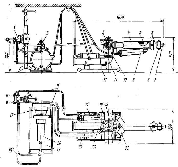
Pictures 1 – Diagram of the hydraulic pulse unit
A working hydraulic pulse unit is the key to high efficiency of production stages and safety of maintenance personnel. Therefore, work before the appearance of obvious breakdowns is not allowed, for this it is necessary to periodically carry out preventive measures to inspect the installation. First, pay attention to the condition of the joints, and monitor their tightness. The breakdown of these elements is indicated by increased efforts in the process of controlling the equipment, water leakage. If a malfunction is found, it is necessary to immediately replace the oil seals, gaskets, cuffs and other sealing elements.
An important part is the operational parameters of installations running on circulating working fluid. This is due to the possible presence of abrasive particles in the liquid, causing premature wear of the device parts. Proper maintenance of the device is the key to long and reliable operation of the installation.
3.2 General provisions
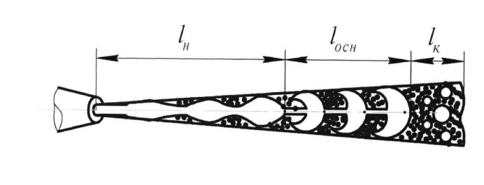
The study of structural changes occurring in pulsed jets of high-pressure water from the moment of their departure into the air to degeneration into a droplet stream is of great importance for understanding the physical processes that determine the change in their hydrodynamic characteristics shown in Pictures 2. Knowledge of the structural features of a high-pressure pulsed jet of water will allow for a more reasonable approach to developing recommendations for their use. The diagram shows a pulsed jet of water produced by an internal interruption of a continuous flow of water and reflecting ideas about the structural changes occurring in it as the distance from the cut to the jet of the forming nozzle increases.

Pictures 2 – The scheme of departure of a pulse jet of water
The mechanism of formation of a pulsed jet of high-pressure water can be described as follows.
The water flow modeled and then formed in the jet-forming nozzle flows into the air from the nozzle, the outlet of which is the initial diameter of the jet d. Further, as the nozzle moves away from the cut, due to the instability of the velocity, the water jet splits into separate jets [8].
In the initial section, the water particles in the jet collide with each other, and as a result, high-pressure zones appear in it. On the surface of the water jet, the pressure is equal to atmospheric pressure, so the surface of the jet is a generator of discharge waves that propagate into the jet and cause radial currents directed from the axis of the jet.
Under the influence of excessive static pressure, turbulent disturbances, as well as due to the unsteadiness of the jet velocity, friction against the air and the release of the gaseous component, expansion occurs impulsively
3.3 Simulation of fluid flow in the actuator of a hydraulic pulse unit
The purpose of the simulation is to study the actual operating mode of the working body with selected optimal parameters under specified conditions. The CAD engineering and graphics software package SolidWorks
and CAD will be used as working utilities in the study.Compass
, as well as calculations and selection of parameters in the MathCad environment.
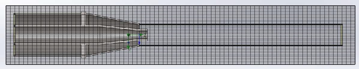
Before starting modeling, it is necessary to create a design model Pictures 3, consisting of an executive body and a glass tube. After pairing the elements, we get a model to verify the study.

Pictures 3 – The project model
In the SolidWorks
program, select create a 3D model. We take the side view as the main view. After that, using the sketch function, we build the contour of the part in the selected plane, and stretch it by rotating around its axis. We choose 10X17H13M2T steel as the model material.
For the convenience of further research, it is worthwhile to develop a model of a glass tube.This model is necessary for further research, since the flow part of the executive body will be studied, while the model must be closed. Under the conditions of analyzing only the model of the executive body, we will get the formation of a jet before the exit holes, which does not reveal the potential of the model to the fullest extent and does not give any ideas about the further behavior of the jet after departure. To simulate further flight and mixing of the liquid, we use the created tube. The choice of tube material is due to its transparency, which will allow it not to stand out against the background of the model and freely observe the flight of the CT
Pictures 4 – The beginning of the simulation.

Pictures 5 – Preview of model parameters.
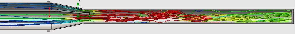
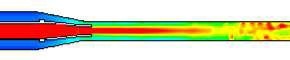
Pictures 6 – Results of fluid flow simulation.
Conclusions
Based on the results Pictures 5, Pictures 6 it can be concluded that this study will significantly increase the speed of calculating the optimal parameters of the working body and installation for their operation under specified conditions.This can later be used to automate the calculation and selection of hydraulic pulse installations for the characteristics of the material being developed.
List of sources
- Фролов В. С., Исследование гидравлических способов разрушения горных пород стационарных и перемещающихся струй / Научные сообщения. - М.: ИГД им. А.А. Скочинского,1975. - №134; c. 30-140.
- Нурок Г. А. Гидромеханизация открытых разработок / Раммэ. - Москва: ГОСИНТИ, 1966. - 45 с.: ил.; 22 см.
- Кляшин Ю. Г. Эффективность применения статического и ударного способов разрушения горных пород различной крепости / Научные сообщения. - М.: ИГД им. А.А. Скочинского, 1974. - №125; c. 26-50.
- Сигеев Е. А., Исследование гидроотбойки пульсирующими гидромониторными струями /Известия ВУЗов. Горный журнал, 1964. – Вып. 2.; c. 30-34.
- Подвидз Л. Г. Энергетические характеристики процесса смешения/ Изв. ВУЗов «Машиностроение», 1976. - №11. – с. 75 – 79.
- Леви И. И.Моделирование гидравлических явлений. М.: Энергия. 1967.– 210 с.
- Носенко В. М., Предварительные испытания модели гидромонитора с подвижной насадкой / Труды института горного дела АН Казахской ССР. – 1963. – Т.43.; c. 90-130.
- Сосновский П. Шахтные водоотстойники. – М.: Госпортехиздат, 1975. – с. 172.
- Попов В М. Водоотливные установки. Справочное пособие. М.: Над-ра. 1990. – с. 254.
- Научная электронная библиотека [Электронный ресурс]. – Режим доступа: https://www.elibrary.ru/defaultx.asp?rpage=https://www.elibrary.ru/item.asp?id=40098639.