


Faculty: Electrotechnical
Speciality: The electric drive and automation of plants
Relevance of the topic. At the present stage of development of automated electric most commonly used are induction motors with cage rotor (IM). This is due to a number of advantages, chief among them:
- simple design, and therefore, ease of maintenance;
- the possibility of adjusting the characteristics identical to those of the DC motor;
- the possibility of obtaining high-quality regulation.
To implement such systems in their structure except for IM should include the transformative device with a programmable logic controller (PLC). In modern drives have a complete choice of control law, depending on process requirements. The range of ways to manage rather wide - from the thyristor voltage regulator to a scalar frequency control or, if necessary, vector control. In this case, the simpler control law, the smaller the number of numerical values of the parameters necessary to locate the drive. Therefore, in the modern complete drives organized by different levels of access to the parameters. For example, in the Siemens 440 Micromaster of five levels of access: from zero to four. Moreover, for 0 - a simple set-up, enough to know the nominal data of blood pressure, indicated on the label. To fine-tune, with 4 - expert level, you need to know the values of all internal parameters of blood pressure: the active resistance of stator windings and rotor, the inductance of magnetization, inductance and electro-mechanical time constant.
Often, the PLC has a built-in algorithm for identifying the parameters of IM, followed by self-tuning regulator control system. This setup is a one-time before starting the drive. However, due to changes in ambient temperature, the values of the moment of static resistance or inertia initial setup of the regulators no longer correct, and requires clarification. This feature is intended to perform a parametric control by checking the consistency of current configuration management parameters (IM) and the introduction of the necessary corrective parallel feedback.
The purpose of master's work is to study ways of parametric control of asynchronous electric drive based on the frequency converter Micromaster 440.
Objectives:
- analysis of the opportunities parameter control law IM depending on the level of access to the example Micromaster 440;
- analysis of existing methods of identification of parameters IM, followed by selection of the most simple and accurate algorithms;
- implementation of the dynamic adjustment коєффициентов regulators in real time.
The scientific significance of the work at this stage of research consists in selecting and analyzing the accuracy of the preliminary identification of parameters of IM, analysis of opportunities parameter Micromaster 440 at different levels of access.
A review of research on the topic in DonNTU showed that the identity of these are given in [1 - 4]. For example, in [2] considered a method of identifying the electromechanical time constant drive speed control systems with state observers, evaluating both static and dynamic aspects of the DC motor with an observer status, which is based on a model of the mechanical part of the drive. With the help provided in [1, 2, 4] techniques can accurately determine the numerical values of the parameters of the mechanical part of the drive that will be used when setting the speed regulator. Also verified that the presented method can be used in the real PLC. [3] reviewed the experimental and theoretical methods for the identification of the electromagnetic parameters. However, in this master's work is not possible to implement the methods discussed, since some of them require special laboratory equipment or complex mathematical analysis of the phase - frequency characteristics.
A review of research on the topic in Ukraine showed that the issues of identification of parameters considered in [5 - 10]. In [5, 10] used the method of identification on the basis of forming power induction motor harmonic signals with a further analysis of their harmonic content using mathematical tools of Fourier transforms. In [9] the problem of parameter identification is solved solution of the system. Software implementation of this method is scientific value, but requires a fairly powerful computing resources. Considered in [9] method of identification is based on the equations Park - Gorev, which in itself introduces an error whose magnitude, in different conditions can reach 10%.
A review of research on the topic in the world has shown that the issues of identification of parameters considered in [11 - 15]. In [11] gives a detailed mathematical description and options for building reference models, methods of direct identification of parameters of the object in the presence of disturbing influences. However, the presented method operates only discrete models. In [12] The algorithm pre-induction motor parameter identification and subsequent adaptation to the time constant of the rotor.
Discussed in [12, 15] methods of identification based on the use of various schemes of induction motors, which in itself makes some errors.
Existing methods of identification can be divided into preliminary and ongoing. To conduct the test (preliminary) regimes of parameter estimation may be required to disconnect the shaft from the working mechanism of IM, and to ensure the required accuracy is necessary to use the sensor speed or rotor position.
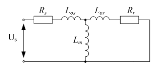
As the electromagnetic parameters to be identified, traditionally considered (Fig. 1) active resistance of stator windings Rs and the rotor Rr, the inductance of magnetization Lm, inductance σLs [12].
The initial data are the phase currents and voltages, which in the real drive can be measured without using additional sensors (Isi, Usi, где і = А, В, С).
Simulink-model of the experiment is shown in Figure 2, which simulates the formation using voltage inverter with PWM voltage required and analyzed the reaction of IM to the test signals.
| Parameter | Rs, Ом | σLs, Гн | Lm, Гн | Rr, Ом |
| Real | 0,7880 | 0,0530 | 0,0481 | 1,2960 |
| Identified | 0,7887 | 0,0520 | 0,0465 | 1,2595 |
| Accuracy, % | 0,009 | 1,9 | 3,3 | 2,8 |
At this stage of pre-tested algorithm parameters identification of induction motor. Detection of any of the parameters of less than 5%, hence this technique can be successfully applied to problems of parametric control.
When writing Autosummary master work was not completed. Finished version of the work and materials on the topic can be obtained from the author or his head after January 2011
Соколов Н.А. Исследование и разработка наблюдателя состояния с адаптацией к изменению параметров объекта управления [Электронный ресурс] / Портал магистров ДонНТУ, - http://www.masters.donntu.ru/2009/eltf/sokolov/diss/index.htm
Идентификация электромеханической постоянной времени в системах с наблюдателями состояния, восстанавливающими статический момент / О.И. Толочко, П.Х. Коцегуб, П.И. Розкаряка, Г.С. Чекавский // Тематический выпуск «Проблемы автоматизированного электропривода. Теория и практика» научно-технического журнала «ЭЛЕКТРОИНФОРМ» – Львов: ЕКОинформ, 2009. – С. 59–62.
Рогозин Г.Г. Визначення електромагнітних параметрів машин змінного струму: нові експериментальні методи. – К.: Техніка, 1992. – 168 с. Мова рос.
Трандафілов В.М., Толочко О.І., Божко В.В. Особливості градієнтного метода ідентифікації моменту інерції електроприводу / В.М. Трандафілов, О.І. Толочко, В.В. Божко // Автоматизація технологічних об’єктів та процесів. Пошук молодих. Збірник наукових праць X Міжнародної науково-технічної конференції аспірантів та студентів в м. Донецьку 18-20 травня 2010 р. – Донецьк, 2010. – С. 260-262.
Использование псевдополигармонических сигналов в задачах идентификации параметров двигателей переменного тока/ Родькин Д.И. // Тематический выпуск «Проблемы автоматизированного электропривода. Теория и практика» научно-технического журнала «ЭЛЕКТРОИНФОРМ» – Львов: ЕКОинформ, 2009. – С. 29–39.
Бешта А.С., Куваев Ю.В., Желдак Т.А., Макуха Ю.Н., Балахонцев А.В. Определение параметров схемы замещения асинхронного двигателя с короткозамкнутым ротором по переходному процессу в обмотке статора //Научные труды КрГПИ «Проблемы создания новых машин и технологий». Кременчуг. - 2000. - №1(8). - С. 157 – 161.
Бешта А.С., Балахонцев А.В., Худой Е.Г. Идентификация координат асинхронного двигателя в условиях дрейфа активных сопротивлений. // Науковий журнал Запорізького національного технічного університету «Електротехніка та електроенергетика», Вип. 2. Запоріжжя – 2005. С.59-64.
Робастный алгоритм идентификации параметров асинхронного двигателя при неподвижном роторе/ Пересада С.М., Ковбаса С.Н., Малько М.П.// Вісник Кременчуцького державного університету імені Михайла Остроградського №3/2010 (62). С.
Півняк Г.Г., Волков А.В. Сучасні частотно-регульовані асинхронні електроприводи з широтно – імпульсною модуляцією: Монографія. – Дніпропетровськ: Національний гірничий університет, 2006. – 470 с. Рос. мовою
Мирсаитов К.М. Метод идентификации параметров ротора асинхронного двигателя на ходу/ Вісник СевДТУ. Вип. 88: Механіка, енергетика, екологія: зб. наук. пр. - Севастополь: Вид-во СевНТУ, 2008.
Изерман Р. Цифровые системы управления. – М.: Мир, 1984. – 541 с.
Виноградов А.Б. Векторное управление электроприводами переменного тока / ГОУВПО «Ивановский государственный энергетический университет имени В.И. Ленина».- Иваново, 2008.- 298 с.
Официальный сайт компании Siemens в России. Предоставлена разнообразная информация о продукции и проектных решениях компании. [Электронный ресурс], - http://www.siemens.com/answers/ru/ru/
Ljung L. System Identification - Theory For the User, 2nd ed / Lennart Ljung – PTR Prentice Hall, Upper Saddle River, N.J., 1999. – 609 pp.
Klaes, Norbert. Identifikationsverfahren für die betriebspunktabhängigen Parameter einer wechselrichtergespeisten Induktionsmaschine. Düsseldorf, 1992. – 100 pp.