about the theme:
“Operating automatic devices with rigid logic on PLIS”
Contents
Introduction
Tasks and Goals
Assumed scientific novelty and practical value
Planned practical value
Existed works overview
Current and planned results
Conclusions
Bibliography
Introduction
Modern digital devices consist of operational machine (OM) and control machine (CM). Operational machine is using for given operations execution, but control machine for joining and coordination of all compound device blocks. Standard digital device is shown on the figure 1.
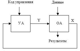
Figure 1 – Structural diagram of digital device.
In practice CM often is implemented as machine with “hardwired” logic (machine Mili and Mura). Operational device control algorithms which are source data for synthesis schema CM is described generally as flow graphs that have lots of characteristics [1].
Today three types of programmable logic device (PLD) are using: simple programmable logic device (SPLD), complex programmable logic device (CPLD) and programming by user - field programmable gate array (FPDA). In SPLD category there are two subclasses: programmable logic arrays (PLAs), programmable array logics (PALs). SPLD consist of two matrixes: matrix “AND” and matrix “OR”. In PLAs both matrixes are programmable, but in PALs matrix “OR” is fixed. CPLD consist of logical gates blocks joined by programmable switching matrix. Modern CPLD in most cases are electrically programmable and save logical structure after switching off power supply. FPGA consist of many configurable logical blocks (LUT) and trace resources providing of there interconnection. It’s necessary to mention Xilinx, Altera, Atmel, Lattice Semiconductor, Cypress Semiconductor [2] as well knows companies developing of CPLD and FPGA chips.
Last years increasing of developing digital devices lead to appearance of in principle new design tools – system of automatic design (SAD). In the beginning they imitated hand development of digital devices by engineer then with appearance of FPGA chips and mass production of programmable logic device the first hardware description languages were developed(80, 90 year of XX century).
Tasks and Goals
• CM and synthesis method developing that is orientated to decreasing of instrument costs in logical schema;
• estimation of implementation complexity developing structure and investigation of effective application branches;
• software developing that support implementation of given synthesis control machines method;
• estimation of further research of synthesized CM in different environments.
Assumed scientific novelty and practical value
Scientific novelty consist in:
• research of CM structure and synthesis methods, directed to decreasing instrumental costs in logical schema;
• identification of application area for developing structure;
• SAD implementation that support realization of given synthesis method for control machines.
Planned practical value
Planned practical value consist in implementation and research of control machines with “hardwired” logic in logical schema where instrumental costs decreased in competence to traditional structures. Developed software for CM synthesis can be used in educational process.
Existed works overview
Today for logical structure description is used high level description languages (Hardware Description Languages - HDL). Most world wide use are VHDL and Verilog languages. However most SAD have special instruments that allow to simplify developing process of control machines, because of control machines implementation complexity with high level languages. For instance module FAS was included to well-known SAD Active VHDL. It has multifunctional graphical interface for control machines description, but description form require knowledge of HDL language. This module also has no structure optimization of obtained machine.
Optimization structure classification is given on Figure 2.
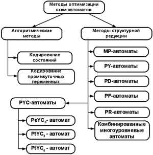
Figure 2 - Optimization structure classification.
However in last years appearance of new, more fast working, containing big quantity logical cells on FPGA crystal change priority for digital devices developing from minimization of instrumental costs in obtained device or maximization of speed for reliability obtained device with maximal speed of production. One method of this problem solving is to use tools which are based on previously developed tools for complex systems development, like model-driven architecture (MDA) and unified modeling language (UML – Unified Modeling Language).
Current and planned results
On the first stage of working under master work control machine structure optimization method was investigated. During machine synthesis process different optimization methods were used in complex: structure reduction, heterogeneous realization, algorithmic transformation.
• table of variables replacement forming;
• optimal coding of machine states;
• maximal coding microoperations;
• device logical schema synthesis.
Next step is to develop software product that allow to synthesis given machine. Developing process led to creation of text file by user containing switching table. Application reads data from the file and converts data to boolean equations and minimize them. As a result application generates output in HDL format compatible with Active VHDL or with free packets like (VHDL Simili 3.0).
Structure of developed system is sown on Figure 3.
Figure 3 – Common application structure.
Principle of system operation: User make source file (File.gsa) that keeps switching table (GS). Data from this file is used by SAD application for transformation and minimization. After analyzing and converting of given information, application generates output file (File.vhdl) with VHDL format that keeps synthesized machine. It can be used in other environments.
Application was implemented using Visual C++ language. It was chosen because of wide set of tools for visual interface building, text file operating and step by step debugging. Application was developed for PC IBM compatible under Windows operating system.
It’s necessary to make a conclusion about advisability of this structure CM usage for different algorithms flowgraphs.
Conclusions
Result of work will be an application that design control machines with “hardwired” logic with decreased instrumental cost in compression with traditional structures. Output data will be stored in a text file with basic characteristic of investigated CM algorithm flowgraph.
Bibliography
1. А.А. Баркалов Синтез устройств управления на программируемых логических устройствах. - Донецк. 2002.
2. В.В. Соловьев. Проектирование цифровых систем на основе программируемых логических интегральных схем. - Москва. 2001.
3. И.Я. Зеленева - "Методы синтеза многоуровневых структур управляющих автоматов на программируемых логических устройствах" - диссертационная работа.
At a writing of the given author's abstract master job is not completed yet. Final end: December 2007.
|


 Русский
 English