

Topicality of work
In metallurgy, a concentration measuring of carbon monoxide is the important in two context problem.
First of all, precise gas analysis can be used in a total system for technological object control. For that analysis data must be presented in digital form and then transmitted in personal computer for following processing. Today, such systems are working in the most part of metallurgical factories with success. They allow to control distantly some technological process. In perspective, we can foresee a creation of automatic control systems for technological process. It will give the possibility not only of observation, whether technological object is working correctly, but also of independent correction of his work.
In the second place, because of high level toxicity of CO, its control is major ecological problem. A blast-furnace gas incineration is carried out on different stage of metallurgical processes, in particular, of blast-furnace production. The carbon monoxide, carbonic gas, dust, oxygen, nitrogen, methane are results of this incineration. If we take into account a global scale of metallurgical factories, we’ll understand how much environmental conditions are critical.
Though deep progress in gas spectral analysis area, gradually many of decisions are standing morally archaic. Today, the choice of modern technical possibilities structure of device is an relevant problem.
The problem solving
We intend to solve the following questions.
First, A struggle with a dust and other particles is a eternal problem of a continuous gas analysis. These particles scatter a radiation and can have an influence on indication of a gas analyzer. We are going to analyse available measuring schemes of gas analyzers, in order to choose optimal scheme.
Second, the absence of microcomputerized processing of measuring results in device is a essential lack of gas analyzers, working on many of metallurgical factories. There is GIAM-14. This gas analyzer, widely used in Ukraine, produces analog signal, which goes on a particularized module next. This module is in a global system, which controls the process. An analysis and storage of an information is in this system. But GIAM-14 hasn’t such functions. In our opinion, it is necessary to have a microcomputerized processing of an information and device of information storage in gas analyzer.
Third, we want to build the mathematic model of measurements. The receiving of radiation source spectrum, which interacts with absorption environment with its spectrum, a description of processes in radiation receiver, etc. are enter in this model. We are going to investigate a few alternative variants of radiation receivers so as to substantiate the choice of the best of it.
In the fourth place, we intend to contemplate a prospects of creation of a gas analyzer, giving a possibility of simultaneous production of two components together - carbon monoxide and carbonic gas. The interest to such device is evident for blast-furnace production, because of blast-furnace gas, using in heating process, has as incineration result CO and CO2 together. An analysis of this components contains an important information about incineration process.
In this abstract, we’ll view the first problem only – the problem of a choice of an optimal measuring scheme for optoacoustic gas analyzer, measuring carbon monoxide and carbonic gas together. Materials for abstract writing were found in [3].
The theoretical analysis
There are two basic schemes of non-dispersing optoacoustic gas analyzers (OAG): a single-channel OAG and a double-channel OAG. A great error of determination and essential influence of a outside conditions are lacks of a single-channel scheme.
A double-channel OAG are more precise and stable. It have a channel, shaping a supporting signal of a compare.
A double-channel OAG (fig. A1) have different variants.
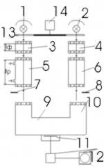
Figure А1 - The main scheme of optoacoustic gas analyzer
1, 2 – sources of pilot radiation; 3, 4 – optical filters; 5 – the working cuvette; 6 – the comparative cuvette; 7, 8 – balancing oven doors; 9, 10 – OA- receiver (beam-receiver); 11 – ОА-sensor; 12 – the amplifier with measuring device; 13 – the obturator; 14 – the obturator drive; lp – the lenth of working cuvette; lф – the lenth of a filter cuvette
The differential OAG with a direct counting out. In this case a modulated radiation from the light sources 1,2 pass through the working absorption cuvette 5 and the comparative cuvette 6 simultaneously, and then goes in OA- receiver with common beam-receiver 10. A radiation, passed the comparative cuvette 6, gives a supporting signal, and OA-sensor chooses THE differential signal between two channels.
In absentia of detection component in working cuvette, the system balances by orificing of a stream through the comparative cuvette, and on the OA-sensor output the signal is equal zero. When the analyzable gas goes for the working cuvette, ОА- sensor fixes an unbalance of channels. A channel unbalance signal is analytical.
Combined OAG with a bilocular OA-receiver. In this case, radiations of the working channel and of the comparative channel are modulated by the obturator 13 in antiphase, and passed radiation goes in OA-receiver, which has two beam-receivers, situated in series. In the first, there is radiation, which falls into the centre of absorption band of analyzable molecules, and in second – which falls into wings of absorption band. They select the configuration and the infill of OA-receiver chambers so that signal phase unbalance in chamber is minimal, when there is absorption of radiation, passed through the comparative channel. When analyzable gas comes in the working cuvette, the signal in a working half-period decreases. Nascent signal of unbalance is a measure of analyzable component concentration.
Compensating OAG, in which a differential signal from the working channel and from the comparative channel comes in on compensative devices. There are apertures and oven doors, weakening a stream, and cuvettes with a variable length, changing a thickness of an absorption gas layer. There is reading by the scale of a compensating device under the signal equals zero. It is measure of content of impurity component.
Laser OAG work by a single-channel scheme, and concrete OAG differ by the using light sources, by the methods of light modulation, by the types of spectrophones: resonant and non- resonant, with single passing of radiation and repeated passing, by configuration of OA-sensors and by type of it. The basic problems of laser OA-analysis get into touch with increase of precision and sensitivity of determination. This gas analyzer’s characteristics are conditioned by possibility of stabilization and calculation of a laser radiation power fluctuation, by background noise decrease of absorption cuvettes windows, by a temperature spectrophone parameters stabilization, and also by possibilities of OAG calibration.
On the fig. A2 you can see the OAG scheme with combined positive and negative filtration. It’s double-beam and double-channel scheme, but it gives possibility to pass analyzable mixture through the working cuvette, covering both halves of radiation stream. It provides high sensitivity under hydrocarbon gas analysis, which have overlapping absorption spectrums. But sensitivity of scheme can be less, if to compare with scheme on fig. A1, because of there are negative filtration elements.
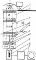
Figure А2 - Scheme of optoacoustic gas analyzer with combined positive and negative filtration
1 – pilot light source; 2 - obturator with driving gear; 3 - filter cuvetta with interfering gases М; 4 - the working cuvette; 5 - zero oven doors; 6 - the comparative cuvette with non-absorptive (ballast) gas Б; 7 - selective cuvette with mixture of analyzable gas A and ballast gas Б; 8 - selective cuvette with mixture of analyzable gas A and ballast gas У, reinforcing OA-receiver signal; 9 - membrane of microphone; 10 - fixed electrode of microphone; 11 - the amplifier with measuring device
At last, we’ll choose measuring scheme, which has the best characteristics for solving our problem. The main demand to measuring scheme is independence its registrations from dust and soot in gas mixture sample. To our mind, the scheme on fig. A2 satisfies in the best way our demand. Actually, the concentration of dust particle in analyzable gas sample, coming into the working cuvette, has an influence on both optical signals of the working channel and of the comparable channel equally. So, gas analyzer registrations don’t depend on dust concentration. But law sensitivity is the lack of this scheme.
Animation 1: File size: 105 кB; frame quantity: 8; review cycle quantity: 10; file format: GIF
Animation 1 - Description of measuring scheme working of О-А gas analyzer
with combine positive and negative filtration
1 – source of pilot radiation; 2 – obturator; 3 - optical filter; 4 – the working cuvette; 5 – the filter cuvette with ballast gas (Б) and analyzed gas A; 6 – OA- receiver (beam-receiver); 7 – recording system
Press F5 to see animation again
At the moment, master work is don’t finished. The ending of it plans in December 2007. you can get the information about the work later by e-mail or by mail. My address:
Ukraine, Donetsk, Vyshnegradskogo-street, 10/11
Literature
1. Полтавец В.В. Доменное производство. М.: "Металлургия". - 1981.
2. Щербаков В.П. Основы доменного производства. М.: "Металлургия". - 1969.
3. Зуев В.Е. Распространение лазерного излучения в атмосфере. М.: - 1981.
4. Павленко В. Газоанализаторы. М.-Л.: - 1965.
5. Бреслер П.И. Оптические абсорбционные газоанализаторы и их применение. Л.: 1980.
6. Немец В.М. и др. Спектральный анализ неорганических газов. Л.: - 1988.
7. Зуев В.Е. Распространение видимых и инфракрасных волн в атмосфере. М.: - 1970.