Raising of task and actuality.
The geographical location of Ukraine explains a large transport potential of our state. Transporting of Russian oil, gas and other liquid and gaseous matters in the countries of European Union is the very important profitable item of the Ukrainian budget. In sew on a country to be plenty of main pipelines and different underground buildings of providing. And a task control of integrity of these buildings is very important. One of made this control - there is control of thickness of isolating coverage that protects a pipeline from corrosion and other harmful actions.
Coverages protect metals from corrosion, execute heatcover, електроізоляційні, decorative functions. Among the indexes of quality of coverages one of major there is a thickness, the possible limits of change of which are determined a normatively technical document. Destroying the methods of measuring of thickness of coverages, for example gravimetric method, the methods of etch microsections do not allow to realize a 100% control of products, they are underproductive and uneconomical. For the non-destructive measuring of thickness of coverages different methods and devices, urgent gaugemeters are used. However, insufficient exactness of industrial devices requires an improvement and developments new actuality of the put task follows from here
A purpose of work: To project is an universal device for measuring of thicknesses of dielectric coverages on electro-explorer basis of different details and constructions on the basis of already existent device which is a prototype for the designed device.
A device must measure the thickness of surfaces of different classes of thickness. With errors less than in prototype, due to indemnification of temperature error.
To the beginning
Review of existent methods of measuring of thicknesses coverages.
The increase of requirements to quality of products which is produced entails the necessity of perfection of facilities and methods of non-destructive control.
General information is about the magnetic method of control. The magnetic method of control is applied mainly for control of wares from ferromagnetic materials, that from materials which are able substantially to change the magnetic descriptions under act of external (that magnetizes) magnetic-field. On a method the receipts of primary information distinguish the followings methods of magnetic control: магнітопорошковий, magnetographic, ferroprobe, effect of Hall, induction.
All of magnetic methods of non-destructive control cavity of metal are based on the exposure of local indignations the fields which are created defects in magnetized ferromagnetic. At magnetized an object a magnetic stream flows on the object of control. In the case of finding of cavity on the way of magnetic stream, there are the fields of dispersion, form and amplitude of which carries information about a size, character, and depth of bedding of defect.
Magnetic transformers. In swingeing majority of cases at magnetic control to be to deal with measuring or indication of the magnetic fields near-by the surface of wares. For this purpose apply different magnetic transformers, from which the most wide distribution was got by induction, ferroprobe, sensor of Hall and magneto-resistive. In магнітопорошкових and magnetographic options apply different powders and ribbons.
Magnetic gaugemeters are intended for measuring of thickness of different coverages on the object of control from ferromagnetic materials or for measuring of thickness of ferromagnetic letters. In magnetic gaugemeters dependence of magnetic resistance of area is utillized magnetic a chain from a gap. On principle of action magnetic gaugemeters can be divided into three groups: tearmagnetic , magnetostatics and induction. A magnetic gaugemeter, based on induction principle of action, is presently produced. Induction gaugemeters utillize onecored magnetic and variable electromagnetic field.
Magnetic gaugemeters. Thickness of unmagnetic coverages (paint, varnish, enamel and other), and also a nickel on steel can be measured magnetic gaugemeters. Magnetic gaugemeters can be divided on tearmagnetic and induction. Work of tearmagnetic gaugemeters is based on measuring of force of tearing away permanent a magnet from the object of control. Pentest and Mikrotest behave to such gaugemeters. They are simple, does not require the source of feed, used measurings on the details of different configuration. A thickness is measured to 20 mm at the error of measuring from 5% to 10% depending on the model of gaugemeter.
Magnetic fault detectors are intended for the exposure of defects as cracks, corrosive ulcers, nonmetallicss but other violations of cavity in ferromagnetic objects, and also measuring of thickness.
For magnetizing of control object a П-like permanent magnet is utillized. The sensor of Hall is located between poles a magnet on central wasp of transformer. Control is conducted by the scan-out of control object with a record and decoding of information of fields dispersion.
General information about the impedance method of control. Acoustic impedance method is the most widespread mean of non-destructive control of connections in multi-layered constructions and wares from laminates.
A method is founded on the differences of mechanical impedance of imperfect and of high quality areas of the controlled good. A mechanical impedance is estimated from the surface of wares in the areas of excitation in him of flexural vibrations of audio or low ultrasonic frequencies. The changes of mechanical impedance convert into the proper changes of electric signal which is processed in the electronic block of fault detector and present on an indicator or utillize for a management executive mechanisms.
The mechanical impedance of Z is name the complex relation of force of F, which operates on-the-spot the controlled area, to middle swaying speed V on this surface in the direction of force: Z = F/V.
A basic application of method domain is an exposure of defects of glue and soldered connections between the comparatively thin (to 3 mm for aluminium alloys and 1,7 mm for steels) edging and element of inflexibility (by a longeron, нервюрою and others like that) or filler (by a foam plastic, honeycombs and other), also defects as stratifications and unglues in non-metal coverages and wares from laminates which bed on a depth to 15-20 ii. His universality, comfort in exploitation, absence of necessity of moistening of the controlled wares, control lightness on curvilinear surfaces, simplicity and availability of apparatus, was instrumental in wide introduction of method.
The transformer of fault detector serves as a device, sensible to the change of mechanical impedance of the controlled object. In impedance fault detectors apply compatible and separately compatible transformers.
Impedansni fault detectors. The sensitiveness of fault detector is determined the sensitiveness of transformer and method of the his initial signal processing in an electronic block.
A large role in the increase of authenticity of exposure of defect is played by the correct choice of informing parameters and methods of the got signal processing.
Peak treatment. The simplest type of the signal processing is peak treatment, where the change of amplitude of the accepted signal is registered.
Phase treatment. The change of signal (to the impedance or speed of distribution of resilient waves) is registered on the change of phase of the accepted signal.
Frequency treatment. The change of frequency of the system in which a transformer is a set frequency link is registered in frequency treatment.
Gain-frequency treatment. The duoparameter signal (in this case on the change of frequency and amplitude) processing allows substantially to promote a sensitiveness to the defect. Especially effective application of gain-frequency treatment is in a імпедансному method, as a presence of defect is caused by a change and amplitudes and frequencies of signal.
Amplitude-phase treatment. The duoparameter signal (in this case on the change of phase and amplitude) processing allows substantially to promote a sensitiveness to the defect.
Spectrology (ACHKH and FCHKH). A spectrum of signal is the most general description of signal. A spectrology allows to register the frequency and phase changes of signal. A spectrology can be utillized and in a impedance method and in the method of free vibrations. An informing parameter is a change of spectrum on an imperfect area in relation to undefect.
General information about the method of free vibrations. Method of free vibrations (MVK) is certain in GOST 23829-85 as a "method of acoustic non-destructive control, based on excitation of freely attenuation resilient vibrations in the controlled object or his part and analysis of parameters of these vibrations". Distinguish the integral and local variants of MVK. In the first oscillation of the controlled object is utillized as unique whole, in the second (to local) - only his parts.
The local method of free vibrations, common for the exposure of areas with violation of connection between the elements of multi-layered constructions, is here examined only, and defects (mainly stratifications) in wares or layers from plastics.
The change of spectrum of free resilient vibrations of the controlled objects serves as an informing parameter in MVK. A spectrum is the generalized description. It is technically simpler to utillize gain-frequency description of spectrum, that is why such method of treatment of information is practically used only.
Advantages of MVK before other low frequency methods is a checking of wares feature from materials with the small modules cabin Boy and by the high coefficients of fading of resilient vibrations (rubbers, to the foam plastic and o. i.) and exposure of defects on a greater depth (to 30 mm in the plastic arts).
Basic methods of shock excitation of resilient vibrations are in the controlled good: 1) mechanical, 2) piezoelectric, 3) electromagnetically acoustic, 4) gas dinamic, 5) optical.
Most apply the first method, as an exciter utillize devices the mobile systems of which are operated by electromagnetic mechanisms.
In mechanical (electromechanics) vibrators the mobile system runs into good during the intervals of time, small as compared to the period of passing impulses.
In shock transformers the controlled object is excited an electromagnetic vibrator.
Ultrasonic method of measuring. Ultrasonic control of thickness of wall of the thin-walled corps and elements of constructions, pipes of oil pipelineis one of major directions of technical diagnostics of the space-air systems. Thus control is conducted both in the workshop terms of enterprises of space-air industry and in repair workshops, hangarages and on outside court. For providing of effective production and safe exploitation of aerospace technique were created and mastered in exploitation a few generations of reflectogauges, intended for the automated and hand control. However greater part from them morally and застаріла physically, and the much again developed own the very substantial failings. To them the low productivity and authenticity behave at the use of piezoelectric transformers (PEP), presence of plenty of influences, absence of the systems of treatment of signals and registration of results of, which reduces control authenticity.
Limitation of ultrasonic method of measuring of thickness
The error of ultrasonic method of measuring of thickness depends on a number of influences which are imposed the followings limitations: by variation of speed of distribution of ultrasonic vibrations (UZK); by the state and geometrical descriptions of good; by quality of acoustic contact at the use of PEP; by magnetic properties and conductivity of material of good at the use of electromagnetically acoustic (EMMA) transformers; by an ambient and other temperature.
Eddy current control method. Eddy current a control method is based on the analysis of co-operation of the external electromagnetic field with the electromagnetic field of vortical currents which are pointed an excitant spool in the electro-conducting object of control (OK) this field. As a source of the electromagnetic field is more frequent all utillized inductive spool (one or a few), by an urgent Eddy current transformer (VTP). A sinewave (or impulsive) current which operates in the spools of VTP creates the electromagnetic field which violates vortical currents in an electromagnetic object. The electromagnetic field of vortical currents influences on the spools of transformer, pointing in them EDS or changing them electric impedor. Registering tension on spools or their resistance, get information about properties of object and about position of transformer in relation to him. The feature of Eddy current control consists in that he can be conducted without the contact of transformer and object. Their co-operation takes a place on distances, sufficient for free motion of transformer in relation to an object (from the stakes of millimetres to a few millimetres). It is Therefore possible to get the good results of control these methods even at high-rate of motion of objects.
<
Eddy currents.
Eddy current a method is used mainly for control of quality of electro-conducting objects: metals, alloys, graphite, semiconductors et cetera. Devices and options which will realize a вихрострумовий method, widely utillized for the exposure of cavity materials (fault detection), control of sizes of OK and parameters of vibrations), determination of parameters and structural state, exposure of electro-conducting objects and for other aims. The objects of Eddy current control can be electro-conducting small twigs, wire, pipes, letters, plates, coverages, in particular multi-layered, railway rails, corps of atomic reactors, marble and rollers of bearings, timber details and much other industrial wares.
Fault detectors which realize a electro-conducting method are intended for the exposure of different cracks, stratifications, measures, shells, nonmetallics et cetera In particular, the fault detector of VD-701 is developed from to the clock-houses of VTP, that allows to control the prolonged objects (pipes, small twigs, will проволікатиму with transversal sizes from 5 to 121mm).
Gaugemeters, based on a вихрострумовому method, are used for control of thickness of electro-conducting letters, tapes, plates, coverages on them, walls of pipes, cylinder and spherical bulbs et cetera, that has superimposed VTP, intended for measuring of thickness of non-metal coverages (paint, enamel, plastic and o. a.) on metallic foundation (aluminium, copper, titan).
Analysing the indicated methods it is possible to draw a conclusion, that all of them have the considerable failings at measuring of thicknesses of dielectric coverages. Therefore I will do a choice exactly of Eddy current method of measuring of thickness. What has a few advantages And substantial from them is that at the relatively small sizes of measuring apparatus he provides a speed and continuous checking of wares feature. Also this method has a most width of opening of cavity, depth of penetration, that slowness, that evidently from a table. Also this method is the undestroying method of control that talks about his advantages.
|
To the beginning
Flow diagram of the designed device and scientific novelty.
Description of blocks which are included in a structure.
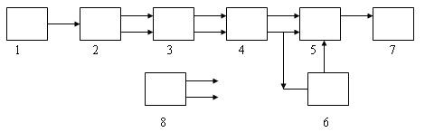
Principle of action of gaugemeter consists in registration of tension from the measuring puttee of transformer (2) which arises up as a result of change of magnetic resistance in a chain «transformer - surface of ferromagnetic basis», picture 4.1. The feed of transformer is carried out from the generator of sinewave tension frequency of 1 кГц (1). Initial tension from the measuring puttee of transformer and equivalent spool acts on two identical channels in which increase and rectifying.
1. Questioner a generator
2. Block of transformer
3. Block of the sinewave signal processing
4. Block of detection
5. Analogo- digital transformer
6. Block of linearizing
7. Digital indicator
8. Power module
After adding up of informative signal with part of supporting tension (adjusting of zero), a difference signal acts on the entrance of аналого - digital transformer (ACP) which operates on principle of double integration. Linearizing of dependence is «initial tension - a digital code» is carried out the method of piece-linear approximation by forming of nonlinear supporting tension of ACP. With the purpose of increase of stability of work of gaugemeter, supporting tension is formed from EDS of the second puttee of equivalent spool.
The temperature error of sensor is caused by two factors: influence of ambient temperature on the electronic components of driver/transmitter (such error is incident to any chart which contains analog elements), and also on active resistance of spool of пробника and connecting send-offs. The change of active resistance of connecting cable and active resistance of spool of tester under act of ambient temperature causes the change of good quality. It is very difficult to compensate such error, as hardness to separate the useful change of good quality which is caused moving of control object, from parasite, caused influence of temperature on a cable and пробник. In the row of original technical decisions which combine analog and digital components is utillized the resulted description of driver/transmitter. On a picture the flow diagram of driver is resulted.
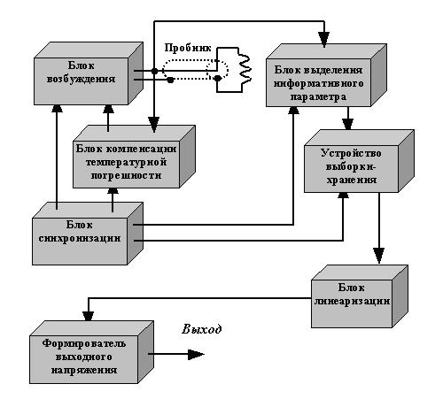
The block of excitation makes the impulsive signal of the special kind for excitation of tester, the block of indemnification a temperature error watches after size of active resistance of cable and spool and in the case of their temperature change definitely corrects the parameters of signal of excitation which practically fully compensates a temperature error. The block of selection of informing parameter carries out the selection of informing signal in the moment of time proper a most sensitiveness. Then informing tension is memorized the device of selection-storage and saved to the next measuring. Synchronization of work of the higher described blocks is carried out the block of synchronization. Frequency of forming of signal of excitation of not less than 1 кГц. Consequently, measuring of distance between the butt end of tester and object takes a place not less than 1000 times in a second, that in obedience to the theorem of Nyquist - Kotel'nikova allows to measure a vibration with frequency to 0,5 kGc. The block of linearizing carries out bringing nonlinear description over to the kind in = kx. The filter of lower frequencies represses present in an informing signal constituents are multiple frequency of diskretization. It is necessary to mark that a filter is not a mandatory functional member, as important only for a spectrology. At the same time spectroanalyzers, as a rule have own FNCH is built-in. The reshaper of initial tension carries out strengthening of initial signal to the set sensitiveness. In addition carries out attachment of output to the positive entrance of nourishing tension, which in drivers (unknown on what reasons) it is accepted to do a general wire.
The feed of gaugemeter is carried out from an accumulator. By the network power module - charge device, accumulator of revives. Exploitation of gaugemeter is possible with a charge device from the network of alternating current 220 In, by frequency 50 Hertzs and in default of accumulator in the compartment of feed.
Structurally a gaugemeter consists of electronic block external transformer which is connected to the electronic block through a socket.
|
To the beginning
Literature.
- "Неразрушающий контроль" Практическое пособие под редакцией В. В. Сухорукова. Книга 3 "Электромагнитный контроль", изд. 3 доп. и перераб.М. 2001г-312 стр.
- "Неразрушающий контроль и диагностика". Справочник под общей редакцией В. В. Клюева, 488 стр.М.-2003г
- Герасимов В. Г. «Электромагнитный контроль однослойных и многослойных изделий» М.: Энергия, 1972. 160с.
- Герасимов В. Г., Клюев В.В., Шатерников В.Е. «Методы и приборы вхретокового контроля промышленных изделий». М.: Энергоатомиздат, 1983. 242с.
- Валитов А.М. «Приборы и методы контроля толщины покрытий. Справочное пособие».М.2003г.-120с.
- Дорофеев А. Л. «Индукционная структуроскопия» М.: Энергия, 1973. 176с
- Г. С. Шелихов "Магнитопорошковая дефектоскопия деталей и узлов". М.:2002г.-220 стр.
- «Словарь терминов по неразрушающему контролю». Под общей редакцией И. П. БелокураМ.:2001г.-226 стр.
- Сухоруков В.В. «Математическое моделирование электромагнитных полей в проводящих средах». М.: Энергия 1975, 152 с.
- «Измерения в промышленности». Справ. изд. В 3-х кн. Кн. 1. Теоретические основы. Пер. с нем. /Под ред. Профоса П. – М.: Металлургия, 1990. – 492 с.
This work is in the stage of development. Final results are expected in the end 2008.
|
To the beginning
|
DNTU>
Master's portal of DonNTU> |
|