
| Individual task | Main | Abstract | Library | Links | Report about the search |

Oleg Kazakov
Faculty of computer information technologies
and automation
Department of electronic technics
Speciality: Electronic systems
Scientific adviser:Vinnichenko N.G.,
senior lecturer, Cand.Tech.Sci.
Theme of master's work: Justification and researching the block diagram
of electronic system, which controls the tension of hoisting installation
ropes
in mine
Abstract on the topic of master's workIntroductionNowadays the creation of the electronic system which controls the tension of ropes is very topical. Item 04.12.1922 of "The rules of safety in coal mines" says about necessity to control the relative ropes overload of multiple-rope hoisting installation in mine [1]. The ropes' imbalance occurs during working multiple-rope hoisting installation (Figure 1) often because degree of elongation varies. The load on ropes is unevenly distributed. This is dangerous because it creates an emergency situation, which is accompanied by a steep fall and lift vessels, destruction of tree trunks, and on human climbs - injury and death.
Figure 1 – Schematic picture of multiple-rope hoist installation in mine In addition, the control of ropes' tension must be implemented to eliminate mismatch of the initial length of rope in the sample. At the case if after a few days the sample rope turns out, that tensions have a great takeoff, and it clearly demonstrates there is a mismatch between the lengths of ropes. This situation requests time-consuming operation of ropes' rearmoring to align their lengths. Thus, the efforts' measurement in the rope is the necessary technological procedure. This problem is not simple, and in fact it does not meet modern demands of using the hoisting installation in mine. Purpose and objectivesThe aim of this work is to research the rope's extension and justification the structure of electronic system which controls the tension of hoisting installation ropes in mine. The tasks of the work are:
The novelty of the workThe novelty of the work lies on the fact that the mathematical model of the rope as a helical cylindrical spring has been clarified for the first time. Based on this researching the elongation most common types of ropes at mines held depending on the load and characteristics of ropes (construction, the diameter of the rope, cross-sectional area). In addition, the block diagram of electronic system which controls the ropes' tension was founded and built. For the first time the modeling of electronic system in the package LabView held. Moreover the advantages of such system were identified, and recommendations were indicated for its improvement. Choice of control methodThe main criteria for choosing this method are: performance accuracy, reliability in various weather conditions and throughout the allowable range of load ropes, ensuring explosion of the technological means, the duration of the work of the independent power supply. A device for measure the tension in the rope (development of MakSRI) was established in the USSR in the early 60's. Work of this device was based on measuring of frequency of transverse vibration of the rope that had limited length. This frequency was directly related to the tension. However, the identification numerical values of the effort led to mixed results because of a strong dispersive nature of such fluctuations [2]. The simplest and most available way to tension measurement is a so-called wave which was proposed in the late 50's by Swedish engineers [2]. The essence of this method is as follows: The need to use arm as a reflected signal receiver and the low accuracy of measurements ordinary stopwatch are disadvantages of this measuring tension method. Limiters tension ropes ONK-1М.U1 use to control the tension ropes of sinking winches (now the device is manufactured by "Sibtenzopribor" Novosibirsk [4]). The tension effort transformation in a proportional electrical signal and indication of the efforts on the remote control is carried out in the device (Fig. 2). The continuously adjustable roller arm system uses for this. The system consists of three rollers, between which the rope is situated with a small inflection on the average roller; two wings, which transmit force to the rollers and mounted on the sensor; and smoothly floating carriage with roller fixed on her middle. The tensoresistance force measuring sensor is used to convert mechanical forces into electrical signal [5].
Figure 2 – The limiter rope's tension of sinking winches ONK-1М.U1 Disadvantages of this constraint are the need to bend the rope and the use of lever-roller system, for which is quite difficult to ensure the accuracy of the action of prolonged dynamic loads during the motion of the rope. A complex of technical means to ensure the safe operation of hoisting installation in mine ("KTS BPU") had been developed in M.M. Fedorova SRIMM. The system is designed to control the tension of ropes, to protect from sagging and overlap, to control actuation of parachute devices, to control cage's location in the groove, to defense against a hard landing of cage, to transfer and to present information for the engineer of hoist [6]. Tension sensor of this complex is located on the rope above the suspended device hoisting vessel. It monitors the load on the basis of rope's elongation. During the operation sensor had showed low reliability. It implemented to control injection of the rope (vertical position of the rope) only. Thus, there is no automated systems that provide reliable control the tension of hoisting installation ropes in mine in Ukraine at this time. Some firms use for these purposes embedded in the pendant strain-gauge devices, magnetoelastic sensors, force dynamometer abroad. However, such instruments are not used wide because of difficulties transferring the information to the surface and rising in price of hoisting installation. It is proposed to continue work on improving the technical means using the method to control the load on the rope on the basis of rope's elongation. This method has such advantages over the previous methods:
Block diagram and animationThe block diagram of electronic system which controls the tension of hoisting installation ropes 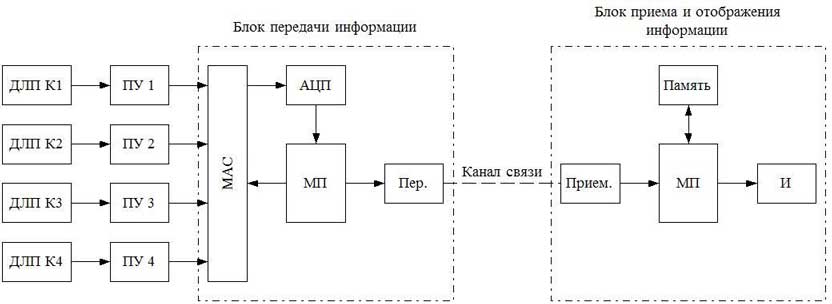
Figure 3 – The block diagram of electronic system which control the ropes' tension The block diagram contains linear displacement transducers (LDT), a preamplifier (PA), which are installed on each of the cables, power transmission unit and unit of receiving and display information. The system periodically polls each of the sensors with analog multiplexer (AM). The signals from the outputs of sensors are fed to an analog-digital converter (ADC), where they are converted into digital form. Next, the digital signals are received at the transmitter (T). Then they are transmitted to the receiver (R) by the communication channel. Microprocessor (MP) controls the interrogation of sensors and the work of unit communication. Thereafter the signal magnitude about each cable's tension goes to the drive information (memory), where this information is retained. The microprocessor (MP) analyzes this data in the unit of receiving and displaying information. The MP issues an emergency light and audio alarm in case of overload on some rope for more than 15% from the average. The process of the electronic system is shown on Figure 4 schematically.
Figure 4 – The process of the electronic system which controls the tension of ConclusionOne of the actual problems for today is the creation of electronic system which controls the tension of hoisting installation ropes in mine. During the writing Master's work this necessity was justified because present technological procedure does not meet modern demands of using hoisting installation in mine. The existing methods to control rope's tension were analyzed. The method to control tension ropes by the size of their elongation was chosen as the optimal. The mathematical model of the loaded rope's elongation was adjusted.The magnitude of expected extensions were installed, depending on the load and the design features of the rope on the example of the rope GOST 2688 – 80. The block diagram of electronic system which controls rope's tension was synthesized. The operation of the system was simulated in the package LabView in the first approximation. Further it is planned to continue research the elongation of the most common types of ropes in the coal mines depending on their design features. It is also necessary to clarify virtual model of the system and explore it taking into account the dynamics in motion of hoisting vessel. Literature
|


