
Contents
- Introduction
- 1. Relevance of the topic
- 2. The purpose and objectives of the study
- 3. Induction motor speed control by regulating the electrical parameters of the pulse
- References
Introduction
The start of inductive motor through direct (contact) connection to power is noted the work of this electric machine on an unstable part of the mechanical characteristics with subsequent transition to stable (working) characteristic. In these conditions, the speed mode of the IM rotor noted the growing acceleration from the beginning of start-up to passing the point of critical sliding. Such intensive acceleration of the IM rotor and, consequently, of conveyor drive pulley creates unfavorable conditions for the operation of a conveyor belt. Thus, the presence of the elastic stage conveyor belt at intensive dispersal of drive pulley leads to appearance of elastic waves of deformation , and significant repetitive dynamic overloads in the towing part during the start of conveyor. (Figure 1.1). [1].
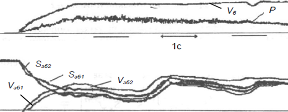
Figure 1.1 – Waveform of starting parameters of the conveyor belt 1L100K-1 when connected directly to the drive motor of 100 kW to the power line [11]:
Vб – the speed of the conveyor drum; Vзб1 ; Vзб2 – speed of section of tape, running off with the drum (the parameters of the 1st is the 2nd sensor); Sзб1; Sзб2 – tension in the portion of the tape, running off with the drum (the parameters of the 1st is the 2 - of sensors); P – motor power
This disadvantage can be eliminated by means of speed control of IM.
1. Relevance of the topic
The lack of effective means to regulate the speed limits the functionality of the drive, causes an increased wear of his elements in connection with a high intensity of acceleration. Therefore, the task of creation of adjustable electric drive of mining machines has a scientific and practical relevance. Means of influence on the IM speed such as an impulse, rheostat, cascade control can also, in principle, be used to provide more affordable technical characteristics of the electric drive mining machines. However, the expediency of their application must be justified in each individual case. In general, the basis of the power semiconductor devices of speed control of the IM, which belong to the most common technical means, constitute power semiconductor key schemes.
The transistor switches differ improved functionality, because they do not require the special devices forced off in DC. Therefore, the task of application of power transistor switches of the devices schemes of the smooth start of electric drive of mining machines has the greatest practical interest.
2. The purpose and objectives of the research, the expected results
The aim of the research is to increase the efficiency of operation of the mine belt conveyor through the application of automation tools of start performed by a scientific substantiation of parameters of transistor regulator.
The main research tasks:
- Perform analytical review of research and development in the field of start control;
- Develop mathematical and computer model of the "transistor regulator – an induction motor", as well as to explore and analyze the processes in it;
- Substantiate and develop structural and schematic diagram of the automation tools start of belt conveyor;
- Justify the requirements for the safe operation of the developed means of automation.
Object of study: coal mine belt conveyor.
Subject of research: induction motor of the conveyor belt drive.
3. Induction motor speed control by regulating the electrical parameters of the pulse
To control the IM speed you can also use the system the pulse regulation, which combines components of rheostatic regulation. The work of scheme is based on the application of a transistor regulator of a voltage stator circuit of a drive IM.
The essence of pulse control is to periodically (pulse) changing the parameters of induction motor chains or a power line. With reference to the asynchronous EP are most often impulsive changing of the supplied voltage to induction motor or resistors in the circuits of the rotor or stator. These methods are mainly used to control the speed, but if necessary they can regulate (limit) the current and the moment of induction motor. Examples of pulse controllers speed of rotor circuit shown in Fig. 3.6.
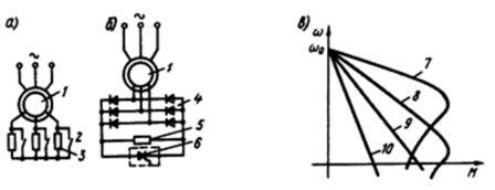
Figure. 3.6 – The structure of pulse rate regulators (a, b) and the mechanical characteristics of the drive (с) [14].
Pulse control of voltage of induction motor stator can be implemented with a transistor or a thyristor voltage regulator. In this case, realized artificial mechanical characteristics similar to those shown in Fig. 3.7.
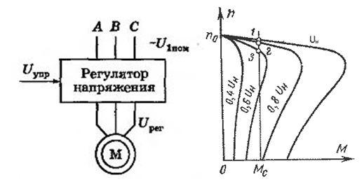
Figure. 3.7 – Block diagram and mechanical characteristics of the induction motor using pulse control of circuit in the stator [15].
For a given speed chart requires feedback to the motor. However, there is a contradiction in terms of speed of reaction scheme of the thyristor voltage regulator for the control commands, in conjunction with the specificity of locking the thyristors. At the same time, transistor devices of smooth start have higher compared with thyristor energy indicators and allow to implement algorithms without launch control binding at the time of transition through zero voltage to generate a sinusoidal output signal format with minimal distortion.
Transistors are completely managed appliances and technical features are bipolar, bipolar with insulated gate (IGBT), field (MOSFET) and field with static induction (SIT). The greatest distribution in the power transistor type IGBT transistors were converters, combining the positive characteristics of bipolar (low loss power when enabled) and field (high impedance) transistors.
To improve regulation of coordinates are enclosed by way of EP using various feedbacks.
The block diagram, compiled on the basis of the description of the object of the research is presented in Fig. 3.8.
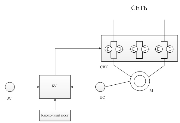
Figure. 3.8 – Block diagram of the transistor voltage regulator
Figure. 3.9 – The transistor voltage regulator work principle
(Animation: 11 frames, 5 cycles of recurrence, 49 kilobytes)
where 1 – control, 2 – speed dial, 3 – speed sensor, 4 – power transistor switch, M – induction motor
Using pulse control can be maintained at a given level of IM speed. Through the introduction of additional units in the scheme in future possible create a task for smoother trigger chart that will increase the start time and the decrease the moment on the IM shaft during start-up.
Thus, created and tested a model to assess the functional properties of pulse control of IM and may be taken into account when designing the appropriate devices.
References
- Савицкий В.Н. Защита от токов утечки в комбинированных распределительных сетях угольных шахт / В.Н. Савицкий, Н.И. Стадник – 13 с.
- Маренич К.Н. Асинхронный электропривод горной машины. Корректировка пусковых параметров / К.Н. Маренич; Сб. науч. тр. горно-электромеханического факультета.– Донецк: ДонГТУ, 1996.– С.176-177.
- Киампо Е.М. Токи утечки в комбинированной электрической сети горных машин / Е.М. Киампо, В.А. Коровкин; Известия вузов. Горный журнал.– 1986.– №2.– С.97-99.
- Белошистов А.И. Проблемы защиты от утечек тока на землю распределительных сетей угольных шахт, содержащих силовые полупроводниковые элементы / А.И. Белошистов, В.Н. Савицкий // Взрывозащищенное электрооборудование: Сб. науч. тр. УкрНИИВЭ. – Донецк: ООО «Юго-Восток, Лтд», 2004. – С. 78-83.
- Колосюк В.П. Токи утечки на землю в системе электроснабжения комбайнов с регулируемым приводом / В.П. Колосюк, Ю.В. Товстик // Уголь Украины. – 2005. – №6. – С. 35-39.
- Ставицкий В.Н., Маренич К.Н. Полупроводниковый преобразователь для автоматизированного электропривода горной машины. // Наукові праці Донецького національного технічного університету. Серія: обчислювальна техніка та автоматизація. Випуск 58. – Донецьк: ДонНТУ, 2003. – с. 122-129
- Груба В.И. Технические средства автоматизации в горной промышленности: Учебное пособие / В.И. Груба, Э.К. Никулин, А.С. Оголобченко. – К.: ИСМО, 1998. – 373 с
- Герман-Галкин С.Г. Компьютерное моделирование полупроводниковых систем в Matlab 6.0: Учебное пособие. – СПб.: КОРОНА принт, 2001. – 320 с., ил.
- Копылов И.П. Математическое моделирование электрических машин: Учеб. для вузов по спец. «Электрич. мишины». – М.: Высш. шк., 1987. – 284 с.:ил.
- Маренич К.Н. А.С. 1824835 СССР, МКИ В65С23/00 Способ управления пуском шахтного ленточного конвейера и устройство для его осуществления. К.Н. Маренич, С.В. Дзюбан, И.Т. Сидоренко и др. (СССР), опубл. 05.02.1990
- Маренич К.Н. Автоматизированный электропривод машин и установок шахт и рудников: Учебное пособие / К.Н. Маренич, Ю.В. Товстик, В.В.
- Слайд 31 из презентации «Асинхронный двигатель» к урокам физики на тему «Электричество». Режим доступа: http://900igr.net/prezentatsii
- Битюцкий А.Ю. Исследование принципа квазичастотного управления асинхронным электроприводом в контексте задачи автоматической расштыбовки скребкового конвейера. Автореф. магистерской работы. [Электронный ресурс] – Режим доступа: Портал магистров ДонНТУ, Факультет КИТА, 2012 г.
- Москаленко В.В. Электрический привод: Учебное пособие / В.В. Москаленко. – 2-е изд., стер. – М.: Издательский центр «Академия», 2004. – 368 с.
- Электронный ресурс «Школа для электрика». Режим доступа: http://electricalschool.info