
Abstract
The contents
- Introduction
- 1. Relevance of the topic
- 2. Purpose and objectives of the study
- 3.Analysis of operating conditions and possible failures
- 4. Proposed model solutions
- 4.1 Engine
- 4.2 Reducer
- 4.3 Crane metalware
- 5 Stationary system composition
- Сonclusions
- List of sources
Introduction
In the conditions of modern requirements to the continuity of technological processes and the reliability of mechanical equipment, changes in the approaches to ensuring the operational reliability of mechanical equipment, including for metallurgical casting cranes, are needed. In this case, the need for trouble-free operation of a complex of metallurgical machines can not be solved by traditional methods of periodic inspection and diagnosis. It is necessary to use stationary diagnostic systems when using a complex of diagnostic parameters. Assessment of the technical condition of metallurgical cranes operating under undefined non-stationary loading can not be carried out using methods used for rotary machines operating in a continuous mode.
1. Relevance of the topic
As part of the metallurgical crane, it is necessary to distinguish three main objects of control: the movement mechanism, the main lifting mechanism, metal structures. Different modes and ranges of measurements in this case are combined with non-periodic loads acting at different time intervals. This allows us to recommend as diagnostic parameters: vibration oscillations, current characteristics and rotational speeds of the drive motors.
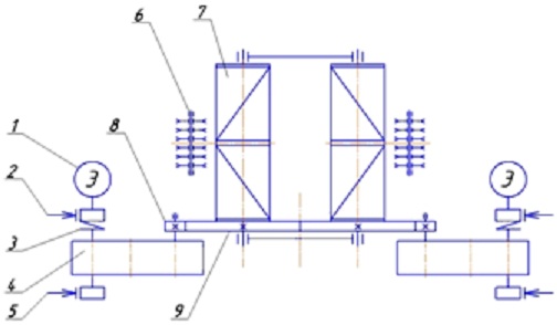
A typical design of the main lifting mechanism of the casting crane is shown in Figure 2. The mechanism consists of two identical mechanisms connected by gear rims 9 of the reels 7, which ensures their equal angular rotation speeds. Each mechanism is driven by a motor 1 and consists of a two-stage reducer 4 and a gear pair 8-9, has two shoe brakes 2, 5 mounted on both sides of the reduction gear 4. The motor shaft is connected to the high-speed gearbox shaft by means of a gear coupling 3. The The mechanism includes a power pulley 6.[6]
At the heart of the construction of the control system, it is proposed to use a block principle that differs by configurable parameters for determining the technical state. The presence of a unifying control unit is necessary. There should be possibilities for expanding control points and analysis functions. This will allow to unify the functions of maintenance, adjustment, operation, use of information and the improvement of the stationary system.
2. Purpose and objectives of the study
The purpose of the system being developed is to increase the durability and reliability of the equipment of metallurgical cranes in operation by timely detection of mechanisms that have increased vibration, determine and eliminate (by repairing) the causes of the vibration.
The system should provide current monitoring and diagnosis of the technical condition of rolling mills mechanisms to prevent sudden failures and ensure the integrity of basic and hull details and machine assemblies. The results of the control should be used to decide on the emergency stop and the need for repair behavior of the mechanisms.[7]
The main objectives of the study:
control and signaling of exceeding the set values: vibration parameters;
use for monitoring the technical condition of current characteristics and rotational speed of shafts of drive motors;
analysis of current values of vibration parameters, recognition of the spectral composition of the vibration signal, the nature of possible damage, and the determination of the trends in the development of injuries;
analysis of temporal realization of the vibration signal and determination of the degree of damage accumulation in impact processes;
assessment of the technical condition of the controlled mechanisms, determination of the time and volume of repair actions;
accumulation and analysis of information on the content of repairs carried out, the effectiveness of impacts, the frequency of replacement elements;
diagnosis of the correct functioning of the stationary system and warning of possible malfunctions.
As part of the stationary system, there should be a block of docking the results of diagnosing with portable instruments and monitoring vibration parameters by stationary sensors. Possible execution in the form of an automated information-diagnostic system for repair of equipment.
It is necessary to provide for the training of specialists directly working with the system, using the information received and the system maintenance specialists.
3. Analysis of operating conditions and possible failures.
The metallurgical crane operates under conditions of variable and non-constant loads at different speeds and different engine torque. The temperature conditions are constant, there are seasonal changes. Increased dust, inside the gearbox housing - the effect of warm mineral oil.
Possible failures are associated with the weakening of threaded connections, a violation of the relative location of parts, the appearance of gaps in the joints and the appearance of a metal contact between the bearing elements, gears. Fixed failures are associated with wear of axles, damage to bearings, gears, weakening and destruction of threaded connections, a violation of the lubrication regime.
4 Proposed model solutions
4.1 Engine
The main type of damage to the mechanical part of the engine is the gradual damage to the bearings as a result of imprecision dyeing or disturbance of the lubrication regime. Damage development time 1 ... 2 months, allow use of trend changes to recognize the occurrence of malfunctions. Violations of centering, timely replacement of rotors having damage, detection of damage to the electrical part of the engines must be carried out by the repair department of the shop during ongoing repairs.[1]
The gradual accumulation of damages during the operation of the electric motor makes it possible to use the values of the general vibration level for monitoring the current state: the rms vibration velocity in the frequency range 2 ... 400 Hz; rms and peak values of vibration acceleration in the frequency range of 10 ... 5000 Hz. Frequency ranges need to be clarified after carrying out vibration studies of engine bearing assemblies.[5]
.Decisions taken: additional lubrication, tighten the threaded connections, replace the bearing. The basis for making a decision is exceeding the values of the vibration of the permissible value, a stable increase in the values of vibration, no reduction in vibration after carrying out repair actions.
It is possible to apply the decision rules given in GOST 25364-97[2]:
the permissible value after the repair is 2.8 mm / s; operation without restrictions - 4,5 mm / s; Operation in a limited time interval (up to 7 days) - 7.1 mm / s; Operation is not allowed if the vibration velocity exceeds 7.1 mm / s.With simultaneous increase in the vibration of two bearings by 1.0 mm / s with the stabilization of the rotation speed, operative measures should be taken to determine the reasons for the change. The increase in vibration of the bearing bearing of the engine by 2.0 mm / s for a period of up to 3 days, or an increase of 3.0 mm / s, regardless of the duration of the increase, should serve as a basis for taking operative measures to identify the reasons for which the engine can be stopped .
The control points are located in the vertical direction, in the lower part of the motor bearing units.
Additional diagnostic parameters for deciding whether to stop the engine: increase the no-load current; instability of the rotational speed.
4.2 Reducer
For the timely detection of gradual and sudden damage, it is proposed to use the values of the overall vibration level and the spectral pattern of vibration to monitor the current state. Controlled parameters when measuring the overall vibration level: rms vibration velocity in the frequency range 2 ... 400 Hz; rms and peak values of vibration acceleration in the frequency range of 10 ... 5000 Hz.
The control of the spectral pattern of vibration is carried out on the basis of the 3-rd maximum values of the components of the vibration velocity and vibration acceleration when operating at a given frequency of rotation. A sign of the change in the spectral pattern is the change in the amplitudes of the components of vibration by more than 2.6 times, the change in the frequency characteristics of the maximum values.
Changing the rotation speed can lead to a change in the spectral pattern, but this is not a sign of damage. Changing the load on the gearbox also changes the appearance of the spectrogram. In mechanical equipment, along with deterministic processes, stochastic processes are also present. The stability of the probabilistic characteristics of the latter is determined by the technical state of the system. The amplitude of the components of the vibration velocity and the stability of the values ??of vibration acceleration may be due to a change in the speed regime or the technical state of the reducer. However, these values ??should remain practically unchanged under stable external influences and have the same type of change when the rotational speed is changed.
The frequencies of possible damage to the elements of the mechanism must be related to the actual engine speed.
Decisions taken: stopping the mechanism, inspecting the mechanism, tightening the threaded connections, replacing the elements. The basis for making a decision is exceeding the values ??of vibration of the permissible value, stable increase in vibration values, no reduction in vibration after repair, sharp change in the spectral pattern compared to previous implementations with constant loading. Changing the spectral pattern of vibration acceleration is the basis for additional inspection of the mechanism. The change in the spectral pattern of the vibration velocity requires an urgent decision on the repair actions to restore the operative state of the mechanism-tightening the threaded connections, replacing the elements. Specification of the maintenance of repair is necessary for carrying out after carrying out of visual inspection of the mechanism.
To select the reference points for the installation of sensors, it is necessary to determine the force action sectors and the strength reserves for the main elements - shafts, gears, bearings. The direction of the installation of sensors requires studies to determine the information content of the various directions for the conditions of the reducer. Determine the informative frequencies of possible damages. Since the frequencies are associated with the elements, you can find some minimum number of control points for diagnosing all the elements of the reducer. It is necessary to perform a contour diagram of vibrations and a search for external bearings.
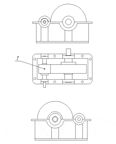
Рicture 3 – Place and order of installation of sensors
(animation: 13 frames, 4 repetition cycles, 134 kilobytes)
Gearbox control points must include the input shaft, intermediate shaft and output shaft bearings. Be sure to provide for vibration control in the axial direction. The use of low-frequency and mid-range allows to reduce the number of control points, since these oscillations easily propagate through body parts. In addition, the monitored elements can be recognized by the frequencies of possible damages.
The proposed arrangement of control points: 1 - the radial direction of the bearing of the input shaft; 2 - the axial direction of the input shaft bearing; 3 - the radial direction of the bearing of the intermediate shaft; 4 -radial direction of the output shaft bearing. The exact location must be selected taking into account the loading zones and the design of the reducer.
In this case, the method of relative comparison of the measured values over the operating time is the preferred method for assessing the technical state. Additional diagnostic parameters for deciding whether to stop the gearbox: increase the no-load current; instability of the rotational speed.
The polling frequency is 1 time per minute, the polling time is 10 seconds, the period between measurements is 100 ?s. To build trends, the hourly value is used, for the archive the daily value, weekly value is selected. The values are selected by the stationary system operator.
4.3 Crane metalware
The state of metal structures largely determines the external influences on the drive mechanisms. The most informative in this case is the control of the temporal form of the vibration signal at the moment of capture of the ascent and the beginning of the movement. This will allow to control the integrity of the beams, the uniformity of the crane movement, the presence of gaps in the elements of the metal structure, the weakening of the fastenings.
The time form is the most informative parameter in assessing the technical state of the mechanisms of short-term and short-term operation modes. Rapid processes with variable accelerations are difficult to diagnose, because the measurement process requires a certain amount of time, during which the measured parameter does not remain constant. In this case, it is advisable to carry out a joint recording of not average but instantaneous values of vibration and obtain for their analysis a time scan.[4]
Arrangement of control points - two single-coordinate sensors installed in the vertical direction in the middle of the main beams and four three-coordinate sensors along the perimeter of the metal structures. It is necessary to provide a quick-detachable connector and mechanical protection against damage to the cable and the sensor. The sensor operates under conditions of an aggressive environment: variable temperature fields, fine dust. This requires the use of stainless materials, dust and waterproof connectors. Intermediate elements can be used to mount sensors. It is necessary to train specialists in the installation, maintenance, replacement and recovery of the elements of the measuring part of the system.
To monitor the condition of the movement mechanism, in particular wheel bearings, it is proposed to use a system for monitoring the current parameters of the engines.
5 Stationary system composition
The following elements should be distinguished in the structure of a stationary system:
- measuring part, includes vibration sensors, it is necessary to provide information on engine speed and current characteristics;
- switching part - cables, preamplifiers and matching devices;
- control units of three types: monitoring of the overall level of vibration, monitoring of the overall level of vibration and spectral components, monitoring of temporal realizations of the vibration signal with the function of monitoring shock processes;
- blocks of visualization and status signaling;
- the general block of the control of a technical condition and diagnosing;
- unit of system state self-diagnostics;
- block of docking diagnostic results using portable devices - an automated information diagnostic system for repairing equipment to account for repairs and characteristic damages.
A very effective addition may be equipment (stationary or portable) for visual inspection of the internal elements of the mechanism, allowing you to perform a clarification of the nature of the damage during routine repairs and preventive maintenance, confirming the correctness of the diagnosis. The effectiveness of the system is determined by the degree of use of information about the technical state. Messages on the current state should become permanent information for operational personnel.[3]
Сonclusions
When writing this essay, the master's work is not yet complete. Final completion: May-June 2018. Full text of the work and materials on the topic can be obtained from the author or his supervisor after the indicated date.
List of sources
1. Обоснование необходимости проведения ремонтов механического оборудования металлургических предприятий,В.А. Сидоров, Донецкий национальный технический университет (Донецк, Украина), http://www.mayster.info/index.php?lang_id=1&menu_id=167
2. ГОСТ 25364-97http://wiki-numbers.ru/gost_pdf/gost-25364-97
3. Информационные основы виброметрии, В.А. Сидоров,Вестник СевГТУ. – Севастополь: Изд-во СевНТУ, 2011. – Вып. 117: Машиноприборостроение и транспорт. – С.157-165http://masters.donntu.ru/2013/fimm/lytaev/library/article8.htm
4. Практика реализации стационарной системы вибродиагностики прокатного оборудования на примере комплекса «КОРУНД» http://patonpublishinghouse.com/tdnk/pdf/2014/pdfarticles/02/11.pdf
5. Механическое оборудование: техническое обслуживание и ремонт / В.И. Бобровицкий, В.А. Сидоров. — Донецк: Юго-Восток, 2011. — 238 с.http://eam.su/2-3-vibraciya-mexanizmov.html
6. Механическое оборудование металлургических заводов/ Магнитогорский государственный технический университет им. Г.И. Носова, 2014г., Стр. 87-94https://elibrary.ru/item.asp?id=22828041
7. О работе подвесок литейных кранов, Щеглов О.М., Сагиров Ю.Г., Суглобов Р.В. - Мариуполь, 25.11.2010г.http://eir.pstu.edu/bitstream/handle/123456789/1396/захист%2013_22.pdf?sequence=1