
Abstract
Content
- Introduction
- 1. Relevance
- 2. Goal and Objectives
- 3. Rope Defects
- 4. Devices for detecting defects
- 4.1 VD-113.5 eddy current detector
- 4.2 PMD-70 magnetic particle flaw detector
- 4.3
Epoch
Ultrasonic Flaw Detector - 4.4
Silvinit
magnetic induction defectoscope - 5. Structuring scheme development
- 5.1 Development Method
- 5.2 Description of the work of the structural scheme
- Conclusions
- List of sources
Introduction
Taking into account the specialization of the region, the way to improve safety in the mining industry is relevant for Donbass. One of the first safety criteria with which workers meet is the safety of lifting equipment. In turn, the safety of the lifting equipment is directly dependent on the condition of the steel wire used.
Steel ropes of mine mechanisms for their intended purpose work in very difficult conditions. Since the damage to the rope carries with it more serious consequences than material, such as human victims, the reliability requirements for such elements of lifting machines and mechanisms as the rope are very high.
1. Relevance
The non-destructive method is more beneficial than taking a rope sample. It allows you to save both finances and time control, which in turn can be a key factor in difficult working conditions.
The basis is a magnetic method of indestructible condition monitoring, improved with the help of a microprocessor-based information processing system added to the prototype circuit of a magnetic flaw detector. The microprocessor will provide communication between the personal computer and the display device of information.
2. Goal and Objectives
The purpose of this work is to develop a block diagram of the system for detecting rope defects, taking into account modern methods of information processing using microprocessor technology.
3. Rope Defects
In the process of using a lifting rope, it is susceptible to damage: a reduction in its own diameter, as a result of the oxidation of metal and breaks in individual wires. Causes of damage can be cage oscillations at the time of acceleration and deceleration, under the action of the air flow, during a long stay of the cage in one place. Defects are divided into two groups: explicit and hidden. Depending on the effect of defects on the steel cable, defects can also be minor, significant, critical.
The danger of a defect is determined by its shape. Defects of the correct form without sharp edges will be less dangerous, so the tension will not concentrate around such defects. With defects that have sharp ends all per turn, such defects will be the site of stress concentration. Such defects increase during operation and may lead to the destruction of the rope.
Existing methods of non-destructive testing are designed to detect defects, violate the integrity of the material of the product; control of geometric parameters and evaluation of the structure of materials.
For hoisting ropes, which are used in vertical trunks, on ascents in inclined workings, periodic instrumental control is provided. If, during the test, the following is detected: loss of the cross-sectional area, which exceeds the allowable level, or wire breaks, the number of which is greater than the allowable in the lay-up step, it is necessary to replace the rope with a new one. Timely replacement of the rope, the state of which has not reached the critical one, may entail unjustified expenses, which are trying to avoid.
In accordance with the rules, the rope to be tested should be inspected at a speed of 1 m / s, the frequency of inspection depends on the use of the rope and varies from one day to one month.
Inspection of the rope (visual inspection)–the most common and simple to implement, gives direct results. But it has significant drawbacks, the main of which is the inability to quantify wear. Boundary-permissible value of the loss of cross-sectional area–is the main criterion for the wear of a steel rope. Another criterion is wire breakage at the lay-up step. Just these criteria inspection can not determine.
The main component of the rope safety is their strength tests at cable test stations (CIS). Rope lengths are checked on the ICC before the rope is used, and then every 3, 6 or 12 months, depending on the application.
The destructible tests of rope lengths on an ICC determine its strength, i.e. gives a direct result. But the downside is that the result does not apply to the whole rope, but to a separate part of it. For retesting, a part of the rope is cut off (usually from a section that is not very susceptible to wear) with a length of at least 1.5 m. For this reason, the result of retesting cannot be considered true with respect to the entire rope. On the other hand, multiple testing of a single rope for a kit may lead to the need to replace the rope in because of its shortening.
Instrumental control using modern flaw detectors allows you to accurately determine the cross-sectional area of ??the rope, as well as determine the number of wire breaks both on the surface and inside the rope. Another advantage of flaw detection is that it allows obtaining objective data on the condition of the rope–magnetograms and protocols. The availability of such data makes it possible to compare the results of past inspections and thereby predict the residual life of the rope service.
Flaw detection allows not only timely replacing a worn rope, but also extending its service life in comparison with tests on EIS. When deciding about the service life of the rope, it is necessary to take into account not only the cross-sectional area of ??the rope, but also take into account the presence of dangling wires. To do this, and there are methods of flaw detection.
All three methods of monitoring the condition of the ropes complement each other, providing the necessary conditions for the safety of their use, subject to the requirements and organization of state control procedures. It is obvious that inspection and defectoscopy belong to non-destructible methods of control, and testing for CIS–to destructible.
4. Devices for detecting defects
4.1 VD-113.5 eddy current detector
The purpose of the flaw detector: work in the field. Detects surface cracks with a width of more than 2 microns, a depth of more than 0.1 mm and a length of more than 3 mm in products made from any material and alloy with a radius of positive and negative coolness greater than 100 mm.
A flaw field rotary converter is used in the flaw detector. Due to this, during the control process, the eddy current transducer can be tilted up to 10° and detached from the surface by 1 mm. The flaw detector is easy to use and does not require highly qualified personnel.
4.2 PMD-70 magnetic particle flaw detector
Purpose of the flaw detector: detection of surface and subsurface defects of products made of ferromagnetic materials with a relative maximum magnetic permeability of at least 40. The flaw detector allows you to control parts of different shape, welded seams, internal surface holes, by magnetizing individual controlled areas or products in general by a circular field created by using a set of magnetizing devices that are powered by pulsed current, as well as direct current. The flaw detector provides demagnetization of parts after inspection. Documentation can be carried out by making a magnetogram of the pattern of defects by removing the print of the pattern on the plastic adhesive tape.
4.3 Epoch
Ultrasonic Flaw Detector
The Epoch Ultrasonic Portable Flaw Detector of General Purpose is intended for performing ultrasonic testing and measuring the thickness of a product from different materials that ultrasounds are carried out.
The flaw detector allows you to detect defects, measure the coordinates of defects and thickness with the issuance of information on the display, measure the equivalent area and the conditional size of defects.
Epoch is a fourth-generation microprocessor ultrasonic flaw detector with a Russian-language menu, color LCD display, with the ability to operate in extreme conditions. Suppose immersion in water to a depth of 1 m.
4.4 Silvinit
magnetic induction defectoscope
Diagram of the magnetic system of the flaw detector is shown in Figure 1.
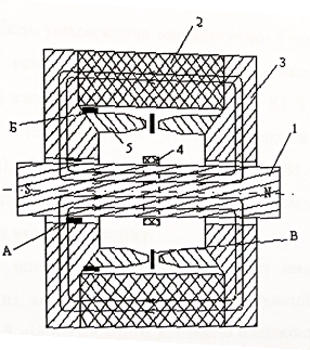
Figure 1–Magnetic flaw detector system
The controlled part of the rope 1 is magnetized by the constant field of the magnet 2. In this case, the magnetic field lines are closed, passing through the rope 1 in the axial direction, through the magnetic circuit 3 and the magnet 2. The resulting magnetic flux depends on the MDS of the magnet and magnetic resistance. This resistance consists of the resistance of the air gap between the magnetic core 3 and the rope 1 and the resistance of the rope section. If there is any heterogeneity in the rope, for example, wire breakage, rust or wear, then the magnetic resistance of the rope section changes, and a stray field forms in this zone. To determine this field, two measuring semi-coils are installed between the magnetic poles between the magnetic poles. In them, the stray field lines of force when the rope passes through the magnetized zone induce electrical signals that, after amplification, enter the recording device or computer. The speed of passage of the rope is in the range from 0.3 to 3.0 m / s. The most optimal speed is 1 m / s.
To determine the places of damage, the half-coils 4 are arranged in such a way that they cover the rope by almost 180 ° each. If, for example, there is damage in the middle of the rope, then there will be a surge in both S1 and S2 diagrams; if closer to one of the half-coils, a burst will appear in only one diagram. The differences in the shapes of the diagrams S1 and S2 make it possible to distinguish external and internal wire breaks.
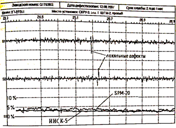
Figure 2 – An example of a magnetogram
5. Structuring scheme development
5.1 Development Method
Magnetic control view is one of the first types non-destructive testing, which was used to diagnose products and industrial facilities. It is used for flaw detection (using magnetic methods, quenching, grinding cracks, sunsets, fatigue cracks and other surface defects with a few micrometers can be detected), hardness determination, structural microscopy, determination of steel grades, measurement of physical parameters of materials (eg magnetic permeability, magnetic susceptibility), to measure coating thickness, mechanical stresses and even chemical analysis.
The basis of magnetic methods of flaw detection is the measurement of parameters of magnetic fields and magnetic characteristics of ferromagnetic materials that can significantly change them under the influence of an external (magnetizing) magnetic field. In this case, the measurements can be carried out both in the applied and residual fields. Depending on the objects of control, various methods of magnetization of controlled objects are used. The parts are magnetized with a constant, pulsed, alternating or combined magnetic field in the longitudinal, transverse or circular direction. The choice of the direction of the magnetic field and the method of magnetization depends on the orientation of the defects. The magnetic field should be perpendicular to the direction of the defect. After control, the parts are demagnetized by heating above the Curie point or by an alternating magnetic field with an amplitude uniformly decreasing from a certain maximum value (equal to or somewhat greater than the amplitude of the magnetizing field) to zero.
In the induction method (magnetic ND method, based on the registration of the magnetic fields of the test object by induction converters), a coil is used to register the stray magnetic fields generated near the defects in the magnetized part, which is moved along the object under test. Electro-motive force (EMF) is induced by the magnetic field of the part in the cat-shk. In the field scattering field EMF changes the electrical signal, which is judged on the defect.
The method is characterized by increased reliability, can work in strong magnetic fields.
5.2 Description of the work of the structural scheme
Based on the foregoing, this system will approximately work as follows.
A permanent magnet provides permanent magnetic saturation of the rope. Induction of a magnetized rope varies depending on the diameter and amount of wire breakage. The value of induction is fixed by MFMS, which converts the field induction into the corresponding voltage. The output signal of the magnetic field transducer is not significant and amounts to units of mV. For further use, the signal requires amplification. An amplifier is arranged on an MCMC chip, which provides signal amplification up to units B at the output of the chip.
The signal from the measuring element through the multiplexer enters the water economy Department, then using the ADC is converted into the corresponding code, which is transmitted to the microprocessor system. The microprocessor processes the signal and outputs the result to the IDD and PC.
The rope length sensor is necessary in order to associate the detected defects with the coordinates of the rope.
Thus, the structural diagram will be:
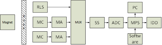
Figure 3 – Structural Diagram
MC – Magnetic Converter
MA – Matching Amplifier
SS – Sample storage
ADC – Analog to Digital Converter
MPS – Microprocessor System
IDD – Information Display Device
RLS – Rope Length Sensor
Software – Special Software
Figure 5 – An example of the system
(анимация: 15 кадров, 168 килобайт)
Conclusions
In the course of the thesis, an analysis of existing methods for detecting defects was carried out.
The master's work is devoted to the actual scientific task of uniting the main methods. According to the results of the analysis, a more suitable one was chosen for the mine line flaw detection under operating conditions. This is a magnetic method. A prototype device based on this method was also chosen, which is distinguished by its accuracy and ease of automation.
Based on the selected method and prototype, a block diagram of the measuring system was developed.
List of sources
- Каневский И.Н. Неразрушаемые методы контроля. Учебное пособие – Владивосток: изд-во ДВВГТУ, 2007. – 243 с.
- Клюев В.В. Приборы для неразрушаемого контроля материалов и изделий. Справочник, 2-е изд., переработка и дополнение М.: Машиностроение 1986. – 352 с.
- Курбатов П.А. Аринчин С.А. Численный расчет электромагнитных полей. – М.: Энергоатомиздат, 1984 – 168 с.
- Матвеев А.Н. электричество и магнетизм. Учебное пособие – М.: высшая школа, 1983 – 463 с.
- Белокур И.П. Дефектология и неразрушающий контроль К.: Высшая школа, 1990 – 207 с.
- Яковлев С.Г. Методы и аппаратура магнитного и вихретокового контроля Учебное пособие. – СПБ: изд-во СПБГЭТУ
ЛЭТИ
, 2003–88 с. - Зубчук В.И. Справочник по цифровой схемотехнике К.: Техника 1990 – 448 с.
- Найденко И.С., Белый В.Д. Шахтные многоканатные установки. – М.: Недра, 1979. – 75 с.
- Бабаджанов Л.С. Бабаджанова М.Л. Меры и образцы в области неразрушающего контроля. Научное издание – М.: ФГУП
Стартинформ
, 2007. – 207 с. - Брынский Е.А Электромагнитные поля в электрических машинах. – Л.: Энергия, 1979. – 176 с.
- Лидовский В.И. Теория информации. – М.: Высшая школа, 2002 – 120 с.