

|
|

In electrical systems are quite common load nodes, consisting of connected to them only synchronous motors. One example is the power supply system of main gas and oil pipelines, which use synchronous motors of high unit capacity up to 12.5 MW with the total number of engines that are connected to the node, up to twenty-four. These knots powerful synchronous load can have a significant impact on levels of short circuit current, static and dynamic stability of power systems. Synchronous load of the node is less constant inertia than the generators of power stations, and characteristics of the excitation system of synchronous motors depending on the voltage supply. This determines the high sensitivity of the synchronous motors to short-planting stress, leads to rapid violations of their stability and subsequent trips. Sharp load may lead to the discharge generators of power stations. As is known [9], the most important operational modes, providing continuity process is automatic starting of pumping jacks engines. The success of self-starting and the character of the process is determined by the electromechanical characteristics of the engine drivers of the supply network and speed synchronous motor at the time of backup power. Depending on the type of production the maximum time interval power can vary from 0,1 to up to several seconds. If the terms of production technology are not allowed food for long periods, then restoring voltage action devices APV and ABP is a risk of non-synchronous activation of the engine when the angle between the EMF of a synchronous motor and the voltage of the network is in the range 120-240° [9, 40, 70]. Emerging at the same currents and moments may cause mechanical damage to the engine or mechanism. Ensure reliable operation of the units of synchronous load requires an individual approach in each case, depending on the requirements of production technology, such as used synchronous motors and mechanisms, the structures of power supply circuits and impossible without a clear understanding of the behavior of synchronous machines with power interruptions caused by short circuits, devices work APV and ABP. In connection with this pressing issue is the development of mathematical models for this type of load nodes and their use in the investigation of transient modes.
Qualifying work of the master performed during 2009-2010. in accordance with scientific direction of department the "Electric stations" of the Donetsk national technical university.
Objective is to develop a mathematical model of the grid nodes with synchronous load and the creation of programs for calculation and analysis of transients.
design scheme for the differential equations describing the transient processes;
develop an algorithm calculating the mathematical model;
implement the algorithm in the programming language Visual C + +.
Method is based on the total differential equations and their numerical solution on a computer for all the main elements of this circuit (feeder, transformer, static load and SD, shunts because r.).
Scientific novelty of this paper is to develop the program language Visual C + + programming to calculate the transients in power nodes with synchronous load. Developed a program for calculating transients in power nodes with synchronous load will be used in designing the course and degree students of the department "Electrical stations". Report on the theme of "A mathematical model of the node synchronous load" presented at the conference to the "Science Day-2010" DonNTU chair power plants. Donetsk, Donetsk National Technical University-2010.
Also gave a report on the Odessa Internet conference in 2010.
A similar issue has already been discussed at the department "Electrical stations" Donetsk National Technical University in 2001, an unknown student Sergei Alexandrovich. The theme of his work magistreskoy read as follows: "Analysis of modes of group deceleration of electric motors". The novelty of this work was to use the existing analytical expressions for previously existing mathematical models taking into account the types of motor load and interchange of stored electromagnetic energy.
Candidates of Technical Sciences A.Besarab, V. Nevolnichenko the simplifed model of computation of electromagnetic and electromechanical transient processes in a multimachine system with the broken network of an arbitrary configuration is developed. Electric engines under consideration are simulated with complete equations, and current network is simulated with equations of determined mode of operation.
At the department "Electrical systems and networks" Faculty of Electromechanical SPbGTU developed mathematical models of transient electric power systems, deep enough to present issues of mathematical modeling of power systems to solve problems of dynamic stability: quantify the effects of saturation have generator damper windings, transients in the circuits of the stator, load characteristics, control of turbines, the department developed a new scientific field: mathematical modeling of transients in power systems containing controlled shunt reactors of any design and analysis of dynamic transients, stability, and surge in such electrical wiring.
Scheme supply node synchronous load is shown in Fig. 6.1, which uses a transformer with split winding 6-10 kV and higher voltage winding connected to power lines. K 6-10 kV busbars except SD connected static load and shunt to simulate varying degrees of remoteness of short circuits. A mathematical model of the transformer and other static elements was discussed in section 2, so the focus of this section be given to determining the parameters of equivalent circuits of various types of diabetes, the transformation of differential equations to the most convenient form for use in constructing a mathematical model of the entire scheme of power and features for modeling different transients. It is known that a synchronous load electrical systems have a significant impact on the character of transients caused by short circuits (K. W.) Switching power supply from one source to another during operation ABP, APW, etc. [1] Suschestvuyutmetody calculation of currents feeding places K. W. of synchronous motors (DM), group self-start after power interruption, but for the calculation of the SD group deceleration mainly used approximate methods based on the results of experiments [3] or on rough assumptions [4, 5], and no refined methods to determine the mutual exchange energy between the individual LEDs, the frequency of rotation of each of them, the magnitude and frequency of the voltage at the node load after the loss of power, as well as shock value of the currents and moments after the second power supply.
In this paper, to fill the above gaps, for a template site synchronous load electrical system (Figure 6.1) proposed a more precise method of calculating the modes of group overshooting DM. [2]

Figure 6.1 - Template site synchronous load power
Method is based on the total differential equations and their numerical solution on a computer for all the main elements of this circuit (feeder, transformer, static load and SD, shunts because r.). Mathematical models of lines, transformers, shunts and loads are used in a form similar to [6]. In order to simplify the mathematical model of the entire site loads, differential equations, DM, in contrast to use as variable values of flux linkage of winding paths DM [7], are recorded on the currents of the stator and rotor, which reduces the amount of payments due to the necessary transition from linkage to the currents at each step of the calculation.
In the proposed method, the unknown currents of all circuit elements are obtained by solving the corresponding differential equations, and used to determine the stresses between the elements arising from the equations of the first Kirchhoff's law in differential form for the nodal currents. Consider first the particular equations of the circuit elements.
Differential Equations three-winding transformer with split winding low voltage can be represented in the form of Cauchy on the currents in the windings in a fixed orthogonal coordinate system X, Y as:

elements of the inverse of inductance of the transformer is defined as:

In equations (1) - (4) using the parameters of equivalent circuit of the transformer: ![]() - respectively active resistance and inductance of the windings of high and low voltages, as well as the mutual inductance of windings
Lm or inductance of the branches of magnetization. Complete inductance coils are determined by the relations:
- respectively active resistance and inductance of the windings of high and low voltages, as well as the mutual inductance of windings
Lm or inductance of the branches of magnetization. Complete inductance coils are determined by the relations:
![]()
Differential equations of static loads of sections 1 and 2 (Fig. 1), shunts for the calculation of currents because r., lines, cross-site links we can write in fixed coordinates X, Y in the form of Cauchy similar [6]:

where ![]()
![]() - respectively active resistance and inductive loads, shunts and communication lines.
- respectively active resistance and inductive loads, shunts and communication lines.
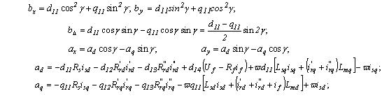
The nodes of the load applied as yavnopolyusnye synchronous motors, and turbo with a massive rotor. Methods of determining the parameters of their equivalent circuits at the list, or the experimental data presented in [8]. We use the most universal equivalent circuit for these types of diabetes, in which the axis of d is exciting winding, and the phenomenon of displacement currents in the rotor is taken into account by using two equivalent damper units on each axis d and q. The original differential equations, written on the linkage to diabetes in the rotating frame of the rotor d, q in relative units are as follows:

where ![]() - voltage, flux linkage and currents of stator windings, excitation and equivalent damper circuits on the rotor axis d and q.
- voltage, flux linkage and currents of stator windings, excitation and equivalent damper circuits on the rotor axis d and q.
Flux linkage of windings in equations (9) - (18) are defined in terms of currents on the relationships:

Complete inductance of stator and rotor are determined by relations:

to exclude linkage of the equations (9) - (18) we substitute in them the expression (19) and obtain a matrix-block form of differential equations for all the contours DM:

for the presentation of the equations in Cauchy form must be left and right sides of equality (21) multiplied on the left of the matrix inverse inductances D, inverse inductances DM:

with elements of the inverse matrix of the relations are:

and b are elements of the matrix of relations similar to (4).
As a result, we obtain the final form of the system of differential equations DM ninth order (23), written in the form of Cauchy and contained in the matrix form below:

To determine the stresses at nodes 1, 2 and 3 of this circuit (Fig. 1) is necessary to make the equation between elements of the scheme, as which we will use the first Kirchhoff's law in differential form, written for the derivatives of the nodal currents in the fixed orthogonal coordinate system X, Y or in phase coordinates.
Since the equations of static elements of the scheme (1), (2), (3), (6), (7) and (8) were recorded in the fixed coordinate system X, Y, and the equations are solved for each CD in its own coordinates d, q, it is necessary to determine expressions for the derivatives of the stator currents of each LED in the fixed axes X, Y.
Given a matrix P for direct conversion of variables in the transition from the axes d, q to fixed axes X, Y and P inverse transition matrix we obtain formulas for derivatives of stator currents SD of axes X, Y and stresses in the axes of the stator board d, q, which requires us to continue:

Replacing in (26) derivatives of stator currents to their values from (23) with (25), we obtain expressions for the derivatives of stator currents SD in the axes X, Y:

where
design scheme for the nodes 1, 2, 3, according to the first Kirchhoff's law, written in differential form, the following expression:

Substituting (28) previously obtained expressions for the derivatives of the currents (1), (2), (3), (6) , (7), (8) and (27) we obtain a system of six algebraic equations, written for the unknown stresses in the nodes of a design scheme in a system of fixed orthogonal coordinates X, Y:


(Done in GIF ANImator, volume - 160 Kb, 7 shots, 5 repetitions)
Using the expression (29) at each step of the calculation are determined by the unknown voltage at the nodes of a design scheme node grid, and then there are the currents of all elements of the scheme of the numerical solution of the corresponding differential equations.
The mathematical model allows to calculate the launch profiles, the group running-out, self-starting, short circuit, to explore modes of synchronous and asynchronous motor loads inclusions. Switching mode, caused by disconnecting the power source, are modeled similarly described method. [6]
1. A method for calculating the modes of group synchronous deceleration loads during short periods of time feeding. The method is based on mathematical modeling of the behavior node synchronous motor load at full differential equations of all elements of the circuit power supply. Differential equations are written for the derivatives of the currents, which simplifies the calculations in the implementation of computer multi-node power system.
2. The mathematical model allows us to analyze the start-up mode, the group running-out, short circuits, self-starting, synchronous and asynchronous switch and synchronous motors can be used in operation and the design load nodes containing synchronous motors.
3. The methods of determining the parameters of equivalent circuits of substitution clearly and neyavnopolyusnyh synchronous motors of the original catalog. For a basis of representation adopted damper units and an array of rotor in the form of multiple-R, L-chains, whose values are found by solving the corresponding systems of equations.
4. To determine the initial values of variables in integrable multimachine power system developed a method for calculating the pre-damage regime based on the equations of all elements for the stationary mode and the method of iterations.
Сыромятников И.А. Режимы работы асинхронных и синхронных двигателей. – М.: Энергоатомиздат, 1984. – 240 с.
Баков Ю.В. Проектирование электрической части электростанций с применением ЭВМ: Учеб. пособие для вузов. – М.: Энергоатомиздат, 1991. – 272 с.
Ойрех Я.А., Сивокобыленко В.Ф. Режимы самозапуска асинхронных двигателей. – М.: Энергия, 1974. – 96 с.
Ковач К.П., Рац И. Переходные процессы в машинах переменного тока. – М.Л., Госэнергоиздат, 1963. – 744с.
Павлюк К., Беднарек С. Пуск и асинхронные режимы синхронных двигателей. Пер. с польск. М., – Энергия, 1971. – 272 с.
Сивокобыленко В.Ф., Лебедев В.К., Кукуй К.А. Математическое моделирование асинхронной нагрузки в режимах группового выбега и самозапуска. – Сб. научн. трудов ДонНТУ. Серия: электротехника и энергетика, вып. 41: – Донецк: ДонНТУ, 2002. – с. 28-34.
Сивокобыленко В.Ф. Переходные процессы в многомашинных системах электроснабжения электрических станций: Уч. пособие. – Донецк, ДПИ, 1984. – 116 с.
Сивокобыленко В.Ф., Костенко В.И. Математическое моделирование электродвигателей собственных нужд электрических станций. Донецк, ДПИ, 1979. – 110 с.5.
Метод расчета группового выбега синхронной нагрузки электрических систем. Сивокобыленко В.Ф., Лебедев В.К., Кукуй К.А. http://masters.donntu.ru/2004/eltf/gorbenko/library/stat1.pdf
Чабан В.И. Основы теории переходных процессов электромашинных систем. - Львов: Вища школа. Изд-во при Львов. ун-те, 1980. - 200 с.
When writing Autosummary work of the master is not complete. The final work can be obtained from the author or supervisor after December 2010.