Subject urgency
In the ever increasing complexity and functionality of devices, as well as the need to diagnose their technical condition of compact testing methods with localization errors are among the most pressing problem-solving techniques test diagnostics. The advantage of these methods is a significant reduction in the amount of information necessary to conduct a test experiment. In the traditional method of compact testing, monitoring is conducted on a "valid - non valid", which is insufficient to identify the type of fault in the failed elements of a discrete device. Necessary and important to determine the time when the output error, that to localize the error in the output test sequence of bits. This method allows to detect and determine the type of failure on the basis of sequences of bits that will accelerate the diagnosis of the elements of discrete devices [1].
Is devoted to developing methods of designing a compact device testing with the localization errors and study their characteristics.
Purposes and tasks
The goal of this work is to develop methods of designing a compact device testing with localization errors and to study their characteristics.
The objectives of the work is to review the existing methods of localization errors and study their characteristics to develop a method of designing a compact device testing.
Alleged scientific novelty
Alleged scientific novelty and practical results are planned to obtain a compact device design techniques to test the localization errors and study their characteristics and to develop new and better devices of compact testing with localization errors, which were not previously addressed in various literature, or not fully considered.
The main content
The paper examines the ways in compact testing with the localization errors in the output test sequence of bits based on cyclic codes, Hamming, Fira, BCH, Reed-Solomon, and also conducted a study of their characteristics.
Cyclic Hamming codes
Central role in the construction of cyclic codes are the so-called generators polynomials. For cyclic Hamming codes as generating uses so-called irreducible polynomials.
The irreducible polynomial is name a polynomial which can not be presented as work of polynomials of lower degrees (analogy with prime numbers). The unbrought polynomials over get out from tables.
The number of check symbols of a cyclic code generator polynomial is equal to the degree and, conversely, the degree of generating polynomial equals the number of check symbols.
The basic idea of a cyclic code is that allowed codeword must be divisible by a generator polynomial without a remainder.
The remainder of the division adopted a code word decoder for generating polynomial acts as a syndrome. If the balance is zero, the decoder believes that no errors occur. In the case of non-zero syndrome, depending on its type, the decoder performs the correction of errors.
There are systematic and unsystematic cyclic codes.
An example of a systematic cyclic Hamming code
Basic data:
number of correctable errors: s=1, dmin=3;
number of information symbols: k=4;
number of check symbols: p = [log 2{(k + 1) + [log 2 (k + 1)]}] = 3;
degree of generating polynomial: deg K(x) = p = 3;
generating polynomial of third degree: K(x) = х3 + х + 1.
 Figure 1 — Schematic diagram of the encoder systematic Hamming code
V — control signal;
C — sync;
R — active reset signal;
In — information signal;
Out — output encoder.
Example unsystematic cyclic Hamming code
Basic data:
number of correctable errors: s=1, dmin=3;
number of information symbols: k=4;
number of check symbols: p = [log 2{(k + 1) + [log 2 (k + 1)]}] = 3;
degree of generating polynomial: deg K(x) = p = 3;
generating polynomial of third degree: K(x) = х3 + х + 1.
 Figure 2 — Schematic diagram of the encoder unsystematic Hamming code
C — sync;
R — active reset signal;
In — information signal;
Out(CK) — output encoder.
Meggit decoder
Meggit decoder not only performs the operation of division by a generator polynomial К(х), but, as the encoder of cyclic codes, the operation of multiplication by the polynomial х р.
 Figure 3 — Functional diagram Meggit decoder for a systematic (7, 4) Hamming code with generator polynomial K(x) = x3 + x + 1.
(Animation: volume - 61.4 KB; size - 628x321, the number of frames - 4, the delay between frames - 80 ms, the delay between the first and last frames - 320 ms, the number of cycles of repetition - infinity.)
RG (n = 7) — digit register 7;
Ind — information signal decoder;
Out — output of the decoder.
 Figure 4 — Functional diagram of a decoder for Meggit unsystematic (7, 4) Hamming code with generator polynomial K(x) = x3 + x + 1.
RG (n = 7) — digit register 7;
Ind — information signal decoder;
Out (H) — output decoder [2].
Cyclic Fire codes
Encoders for Fire codes constructed similarly encoder for cyclic Hamming codes. The differences lie in the implementation of the decoder.
The generator polynomial Fire code has the form:
F(x) = (x 2b-1 + 1)* P(x),
where Р(х) – a primitive polynomial, deg P(x) = b, b – length of the package correctable errors. The code length n = (2b - 1)*(2b - 1), the number of check symbols p = 3b – 1, the number of information symbols k = n – p, the parameter measures inefficiency code z = b - 1.
An example of a systematic cyclic Fire code
Basic data (105,94), b=2, g(x) = (х7+1)*(х4+х3+1)=х11+х10+х7+х4+х3+1.
The decoder takes the form:
 Figure 5 — Functional diagram of the decoder Fire (105,94) for the systematic code
An example of a systematic cyclic Fire code with interleaving
Basic data (105,94), b=2, g(x) = (х7+1)*(х4+х3+1)=х11+х10+х7+х4+х3+1.
j=2, interleaving code (210,188), b=4, g(x) = х22+х20+х14+х8+х6+1.
The decoder takes the form:
 Figure 6 — Functional diagram of the Fire decoder (210,188) for a systematic code with interleaving j = 2
The method of interleaving with degree j can be longer Codes Correcting Bursts of length (j*b). In this case, if the data code has parameters (n,k) and generating polynomial g(x), then the new parameters will be (jn, jk) and g(xj) respectively [2].
Functional diagram of a Fire decoder for unsystematic code is constructed similarly as for the Hamming code.
Cyclic BCH codes (Bose-Chaudhuri-Hocquenghem)
Encoders for BCH codes are constructed similarly encoder for cyclic Hamming codes. The differences lie in the implementation of the decoder.
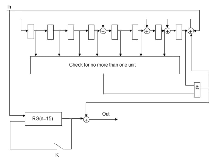
Consider the implementation of the decoder in the example BCH code (15, 7), correcting two errors: a generator polynomial В(х) = х8 + х7 + х6 + х4 + 1, the code length n=15, number of check symbols p = deg B(x) = 8, number of information symbols k = 7.
The decoder takes the form:
 Figure 7 — Functional diagram of a decoder for a systematic BCH (15, 7) code
The decoder works 3n clocks. The first n clocks: generated syndrome code word is entered in the buffer register. Second n clocks: corrected one of the existing errors and the code word once again written to the buffer register (key К is closed), the third n clocks: the second error is corrected. Modification of the syndrome for this code is required.
The disadvantage of this circuit implementation is the inconsistency of the encoder and decoder. Coder must wait 2n clocks, while the decoder will perform a correction.
To overcome this limitation using the conveyor version of the implementation of the decoder [2].
The method of interleaving with degree j for the BCH code decoder is constructed similarly as for Fire codes. A functional diagram of a decoder for the BCH code is constructed similarly unsystematic, as for the Hamming code.
Cyclic Reed-Solomon codes
Reed-Solomon codes are a special case of BCH codes. The main difference of Reed-Solomon codes is that, as a symbol appears, not binary symbol (one bit), and an element of the Galois field (several bits).
The generator polynomial of Reed-Solomon error-correcting s, must contain 2s roots:
{aj0, aj0+1, aj0+2,…, aj0+2s-1},
where j0 – constructive option. Typically, j0 choose to 1. Then the set of roots of a polynomial takes the form {a, a2, a3… a2s}.
For Reed-Solomon error-correcting s, generating polynomial is:
RS(X) = (X - a)(X - a2)(X - a3)…(X - a2s).
With such representation generates a polynomial has roots (a, a2, a3… a2s).
Summary of error-correcting coding is the introduction of a primary code redundancy. Therefore, noise-resistant codes are called redundant. The task of error-correcting coding is then added to the information symbols of the primary codes of additional symbols to a receiver of information can be found and corrected errors that occur under the influence of interference in the transmission codes for communication channels. The formula of calculation of redundancy takes the form R=p/n, where p - the number of check symbols, n-length code. p - value is calculated using the formula p=degRS(X)=2*s.
The length of the correctable error package for sequential code without any restrictions is t=j*b-(b-1) for interleaving Reed-Solomon Galois field GF GF(2b) with the parameter j [8].
The scheme of interleaving Reed-Solomon code can be obtained from the scheme data code, inserting extra memory for each element j-1 elements. For example, for the field GF(23) for interleaving with the parameter j=2 each triad of memory elements should be replaced by two series-connected triads [10].
Order from (n, k)-code to get (jn, jk)-code, choose from source j arbitrary code words and enlarge the code words, alternating characters. If the data code for correcting arbitrary error burst of length d, it is obvious that the resulting code will correct all error bursts of length jd. For example, applying the method of interleaving to four copies (31, 25)-correcting code error burst length 2, we get (124, 100) - code that can correct the error burst length of 8 [3].
Assume that the data code generator polynomial g(X). Then the generator polynomial is obtained by interleaving the code is g(Xj). Note that the interleaving of several information symbols followed by a multiplication of polynomials on g(Xj) gives the same code word as the multiplication of each source of information on the polynomials g(X) followed by interleaving of these words (n, k)-code [4].
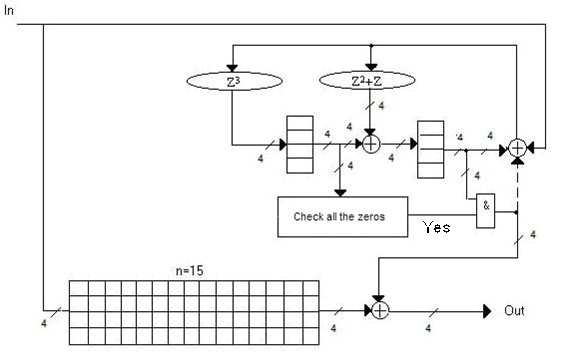
Figures 8-9 are examples of hardware implementation of decoders Reed-Solomon codes with a Galois field GF (8) and GF (16), correcting single errors.
![Functional diagram of the decoder of Reed-Solomon code for the Galois field GF (8) for s = 1 [9]](../diss/decoderruk.gif) Figure 8 — Functional diagram of the decoder of Reed-Solomon code for the Galois field GF (8) for s = 1 [9]
Figure 8 — Functional diagram of the decoder of Reed-Solomon code for the Galois field GF (8) for s = 1 [9]
 Figure 9 — Functional diagram of the decoder of Reed-Solomon code for the Galois field GF (16) for s = 1
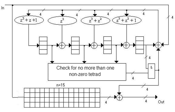
Figure 10 shows an example of hardware implementation of the decoder of Reed-Solomon code with a Galois field GF (16), correcting double errors.
 Figure 10 — Functional diagram of the decoder of Reed-Solomon code for the Galois field GF (16) for s = 2
Figure 11 shows an example of hardware implementation of the decoder of Reed-Solomon code with a Galois field GF (8) and interleaving j = 2, correcting single errors.
![Functional diagram of the decoder of Reed-Solomon code for the Galois field GF (8) and j = 2 [9]](../diss/decoderr3uk.gif) Figure 11 — Functional diagram of the decoder of Reed-Solomon code for the Galois field GF (8) and j = 2 [9]
Figure 11 — Functional diagram of the decoder of Reed-Solomon code for the Galois field GF (8) and j = 2 [9]
The device of compact analysis
A compact analysis device (CAD) with the error bursts localization of length b can be constructed on the basis of decoder of the selected code. When CAD is constructed on the basis of the cyclic n, k-code (n - is a code length, k is a number of information code symbols, n-k is a number of check code symbols) then the residue of division of the sequence analyzed by encoding polynomial g(x) may be used as a compact estimate. The sequence analyzed is represented in the form of the polynomial xn-k. When CAD is constructed on the basis of the shortened s creating a polynomial n-i, k-i-code, the residue of division of the sequence analyzed by encoding polynomial g(x) may be used also as a compact estimate. In this case, the sequence analyzed is represented in the form of the polynomial multiplied by polynomial xn-k+i. The division and multiplication operations are implemented with linear feed-back shift registers [3,5,6]. The advantages of applying shortened cyclic codes for the purpose of the compact analysis are reduction in time of the error burst localizations, the possibility of applying CAD for various sequence lengths analyzed, potentialities of applying the Fire codes to localize large errors bursts [1,7].
Before proceeding to a comparative analysis of codes let us formulate criteria of effectivess of their applications for the purpose of compact testing. These criteria and indices characterizing them result from requirements for the compact analysis devices: a signature length and hardware expenditures should be minimal; the length of the sequence analyzed should be resonable (no less than the length required, but not too long); the speed should be maximal [1,7].
The method of designing a device of the compact testingt (DCT) involves the following steps:
–analysis of the object diagnostics (device type (combinational, sequen-vatelnostny, one input or multiinput), type of test (probe, a device built-in test), defective or knowingly failed, error caused by intermittent faults, permanent faults, random faults, the nature of the error distribution with different multipleness )
–analysis of test actions (exhaustive testing (combinational circuits), pseudorandom testing, synthesized tests, random tests, etc.). For the synthesized test error probability of low multiplicity is maximum. For intermittent fault probability of single errors is greatest. For a known good sites single point of failure probability is maximum, while during the second test detection may be different;
–select the code to implement the compact test.
For random failures and intermittent failures is enough to choose the Hamming code. For constant failure to use appropriate codes Correcting Bursts (Fira codes or Reed-Solomon codes). All these numbers refer to blocks of code. Tree codes for these purposes do not apply. In addition, apply for these purposes such codes, such as turbo-codes, which, although a block, for they use encryption techniques developed for tree codes;
– Development of DCT by cyclic block codes.
Basis DCT is decoder selected code without the buffer register is not a conveyor implementation. For localization errors using computers. Before the compression test reactions reference signature is loaded into the generator syndrome. In some cases, not for shortened codes feasible alternative implementation of the generator syndrome (scheme of division of a polynomial with external adders in the feedback circuits). Depending on the length of the test used decoder for shortened or not shortened codes;
–obtaining compact reference count
Standard compact estimates are calculated either analytically or formed with the help of a known good device and the encoder selected code. Download reference sequence DCT can be either parallel or sequential manner as before the test, and after, the main way to consider the principle of superposition, that is, when matching compact character by character count result of addition of zero, and for parts that is different from zero.
–analysis characteristics of different implementations code.
For example, Reed-Solomon codes. Description of characteristics can be viewed at the following links [4,,
8,
10].
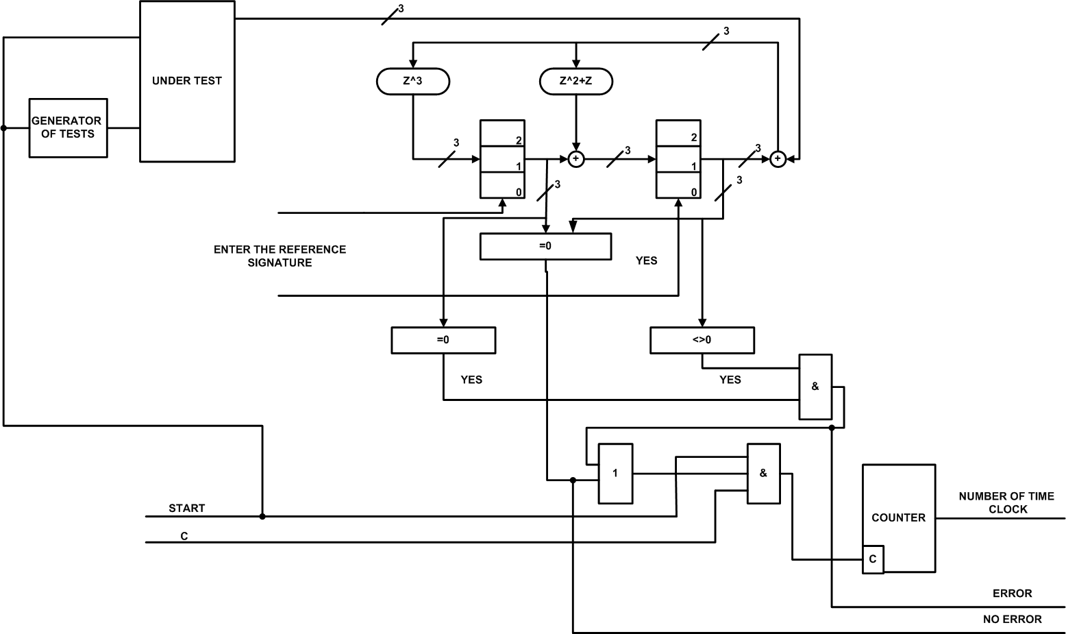
 Figure 12 — Functional diagram DCT—based decoder of Reed-Solomon code for the Galois field GF (8)
Description of the functional circuit DCT shown in Figure 12
The circuit begins with the input reference signatures in the memory elements of the generator syndrome Reed-Solomon, then the signal generator Start is run tests and the tested circuit. Test generator sends a test sequence on the test circuit. The reaction of the tested circuit is fed to the syndrome generator of Reed-Solomon, where the division by a generator polynomial and the addition of one character with a reference signature. Then the check bits from the syndrome generator of Reed-Solomon to zero, if yes (all zero), then the signal is given no errors, otherwise the detection in a single block of memory elements to zero, and the other is not zero in such a manner as shown in scheme, it is issued to signal an error and the computer shuts down on the number of cycles, when the error occurred.
Conclusion
Thus, in the terminology of noise immunity coding, the efficiency of implementing codes for the purpose of the compact testing needs to be compared against the following indices. Firstly, the number of the check symbols of n-k code should be minimal. In this case, the signature length and hardware expenditures will be minimal too. Secondly, code length n corresponding to the length of sequence analyzed should be long enouth [1].
References
1. Дяченко О.Н. Компактное тестирование запоминающих устройств с локализацией пакетов ощибок // Электрон. моделирование.- 1996.- 18, №6.- С.43-48.
2. Дяченко О.Н. Теория информации и кодирования // Электронный конспект лекций.-2008.
3. Блейхут Р. Теория и практика кодов, контролирующих ошибки / Пер. с англ. - М.: Мир, 1986. - 576 с.
4. Юрьев И.В., Дяченко О.Н. Определение оптимальных параметров кодов Рида-Соломона // Інформатика та комп'ютерні технології / Матеріали V міжнародної науково-технічної конференції студентів, аспірантів та молодих науковців - 24-26 листопада 2009 р., Донецьк, ДонНТУ. - 2009. - С. 82-88.
5. Питерсон У., Уэлдон Э. Коды, исправляющие ошибки / Пер. с англ. - М.:Мир, 1976. - 575 с.
6. Касами Т., Токура Н., Ивадари Е., Инагаки Я. Теория кодирования / Пер. с яп. - М.: Мир, 1978.-576 с.
7. Dyachenko O.N. Memory Compact Testing with Error Burst Localization // Engineering Simulation.- 1997.- Vol.14.- pp.907-915. (0,63 др. арк.)
8. Дяченко О.Н. Аппаратная реализация и корректирующие возможности кодов Рида-Соломона // Наукові праці Донецького національного технічного університету. Серія "Проблеми моделювання та автоматизації проектування динамічних систем" (МАП-2007). Випуск: 6 (127) - Донецьк: ДонНТУ. - 2007. - С.113-121. [Электронный ресурс] &mdash Режим доступа: http://www.nbuv.gov.ua/portal/natural/Npdntu/Pm/2007/07donrsc.pdf
9. Дяченко О.Н. Компактный анализ над полем GF(3) // Наукові праці Донецького національного технічного університету. Серія: Проблеми моделювання та автоматизації проектування динамічних систем (МАП-2002). Випуск: 52.- Донецьк: ДонНТУ.- 2002.-С.162-167. (0,38 др. арк.)
10. Юрьев И.В., Дяченко О.Н. Влияние параметров поля Галуа и перемежения на избыточность кода Рида-Соломона // Інформаційні управляючі системи та комп'ютерний моніторинг (ІУС та КМ-2010) / Матеріали I всеукраїнської науково-технічної конференції студентів, аспірантів та молодих вчених - 19-21 травня 2010 р., Донецьк, ДонНТУ. - 2010. - С. 164-168.
Note
The master’s work has not completed yet. Completion date is December 2010. Full text can be received from the author or his scientific advisor after this date.
| 


