
Physics and Metallurgy faculty
Speciality: Processing of
metals with pressure
To improve the manufacturing efficiency at the Makeyevka Metallurgical Plant, the light/medium-grade mill 390 was put into operation in July 2009.
The mill construction has a long history; its origin goes back to the last years of the USSR and the Soviet section rolling production being oriented on firm SKET. Underbuilding in the existing premise of the old section rolling mill and first equipment procurement refer to 1994-1995 – the post-launch period of the wire mill 150 delivered by the SKET.
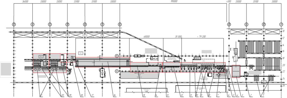
In accordance with the SKET project, mill 390 is an uninterrupted, single-lane, uncanted 18-cage mill, originally planned as medium-grade and developed for the use of the in-house rolled billet with a 156х156mm cut, and the production of outputs in the rods of 6-12m. The layout drawing of the mill 390 is shown in Figure 1.
The minimal shapes of designed assortment were as follows: round rolled metal with a 20mm cross section, square stock with a 18mm side, hexahedral stock with the inscribed circle diameter of 20mm, reinforcing bar for concrete structures №14, equal-flange angle bar of 32х32х4mm.
In the 1990s the absence of strategic investor led to the construction termination. It was resumed in 2006 after the appearance of the Smart Holding, a new strategic investor, and the conclusion of the contract for the goods and technology additional delivery with a SKET successor, Magdeburger Walzwerk Engineering (MWE).
Due to the changes in market conditions, the new contract stipulated the expansion of the mill assortment towards merchant-mill products and fittings.
The prime provider involved in equipment delivery German firms, such as LOI (specializing in heating furnaces and heating automation) and Transresh (specializing in electric drives and automation of the 1st and 2nd levels). In the development of the technology of starting assortment rolling, including a double-strand "rolling-division", of the construction of bivouac slip fittings, and of the automated system of operations management (SOM) there took part the NGO Doniks from Ukraine. Roller fittings for rolling round and angular profiles were delivered by the Swedish company Morgardshammar AB.
The challenge of assortment expanding was settled by the use of two dimension types of the billet - 150h150h7500…11800 и 125х125х х7500…11800 mm. The billet with a smaller cut is used for the production of round profiles with a Ø 12..14 cross section and reinforcing bar № 8…12.
The designed producing capacity of the mill ranges from 600 000 to 700 000 tons per year, depending on working assortment.
The designed assortment of the mill-manufactured products is as follows:
brand:- carbon Ст0, Ст3, Ст4, Ст5, Ст6 according to the State Standard 380-94 and Ukrainian State Standards 2651-94;
- carbon structural quality 08, 10, 20, 30, 40, 45, 50, 60 according to the State Standard 1050-88;
- steel for reinforcing concrete constructions 10GT, 35GS, 80S according to the State Standard 5781-82;
- alloy structural steel 45X, 50X, 35G2, 30HGS, 38HGSA, 38HS, 30HGT, 40HN according to the State Standard 4543-71;
profile:
- reinforcing bar for the concrete constructions of A240S, A400, A500, A800 classes №8…36;
- rounds of a Ø 12...60 mm cross-section;
-square stock with a 14...45 mm side;
- hexahedral stock with the inscribed circle diameter of 14...48 mm;;
- equal-flange angle bars from 25х25х3 to 63х3х4...6mm;
-unequal-flange angle bars from 45х28х3...4 to 63х40х4...8mm;
-channels № 5, № 6.5, № 8;
-rolled metal for springs of 75х8, 75х9,5, 90х10, 90х12 sizes.
According to the composition and equipment location there is the following operating procedure in the mill.
Before putting in the furnace billets of the same melting are being weighed on the charging roller table and measured, each melt receives its lot number. Billet heating is carried out in the systematic combined heating furnace with walking water-cooled girders and a walking beam. The potential output of the furnace is 120 tons per hour on the 150х150х11800mm billet.
On coming out of the furnace through the collecting roller table a billet is fed to the roller-thermostat meant to stabilize and equalize the temperature over the cross-section. The potential loss of temperature of the back end inside the thermostat equals 40°С.
To the first cage of the mill a billet is fed with the help of the injection machine. In emergency cases in the roughing mill group billet cutting is carried out with air discontinuous billet shears set before the first cage.
Roughing train includes three horizontal (1, 3, 5) and three vertical (2, 4, 6) cages. The medium group includes six cages, of which three horizontal (7, 9, 11), one vertical (10) and two hybrid (8, 12). Finishing train consists of two horizontal (13, 15) and four hybrid (14, 16, 17, 18) cages. The main type of transshipment in the mill is the alternation of cages. In the roughing train the alternation of cages is performed by the bridge crane, and in two other trains – with the help of the group cage alternating machine. The roll change, as a rule, is carried out on test benches. In an emergency the change can be performed by the rolling cartridges in the mill.
Between roughing and medium, medium and finishing trains there are emergency slider-level shears, which perform the dressing of the front end of the breakdown. Rolling in the roughing and medium trains is carried out with a minimum tension provided by the automated system of tension control. Between medium and finishing trains and between all of the cages of the finishing group there have been installed vertical air loop-regulators, ensuring rolling without tension.
Table 1 presents the parameters of rolling mills, engines, driving lines and the possible parameters of rolling equipment.
After the finishing train there is a 29m section of accelerated cooling (SAC), designed for the heat treatment of rolled metal with the rolling heater of a Thermex design (Germany). The device for accelerated cooling consists of six independent sections, each 4,5m long, mounted in roller lines on platforms with parallel-installed roller sections. The platforms of a segmental type enable the input of a section – a cooling device or a roller – into the mill workflow by rotating it to the angle of 25° with a remote command. In addition, the project provides for placing a precooling device after cage 16 to thermostrengthen large rebars and achieve a high strength grade.
The combination of three dimension types of cooling pipes of 33, 42 and 48mm gages and two dimension types over the cooling length (long and short) allows enough flexibility to adjust cooling time for the guarantee of specified mechanical properties. The reinforcement of small rebars, rolled in two lines, provides two double-strand sections of a 33mm gage (long and short).
After the device for accelerated cooling at a 4,5m distance there are dual-system dividing shears, ensuring the cutout of mill and reinforcing bar of a 50mm diameter into multiple lengths at 2,3 – 11,6 m/s by a crank-lever system, and at 11,7-17 m/s – by a crank system. The transportation of hot rolled metal from the dividing shears to the receiving table is carried out through the approach table. The length of the cooling conveyor rack is 102m, it is equipped with a tightening device aimed at leveling leading ends of beams, and a storage device for cooled rolled metal layers.
After cooling in the cooling bank and layer accumulation a rolled metal in layers is transmitted to the cold sawing flying shears, and at the same time the structural shapes before cutting pass through the mangle launched in the shearing line. The speed of layer transportation is set either with a pressure roller (while cutting mill and reinforcing bars), or with a mangle. Semifinished section lengths through a collecting roller table are transported to the cross transfer, equipped with a device for leveling beam ends, a metering device and a tilting device, which is meant for the turnover of the angle layers while packing it in rectangular packages.
After the cross transfer there are two knitting machines, delivered by Sund Birsta AB (Sweden), that strap packages with a rod. Strapped packages are transported to a collection rack, in front of which there are scales for weighing packages.
The main principles of the development of calibrating circuit were the gage versatility in the use of an uninterruptedly-casted or a rolled billet, the minimum number of oval and round gages, the maximum uniformity of deformation in rough passes, the maximum utilization of the exhaust capacity of roughing and medium groups of cages. These requirements were fully met by a rough pair "box – box oval" and the exhaust system of gages "oval – circle". Thus, for the entire assortment of rounds and rebars there were chosen 18 oval dimension types, 15 dimension types of a round former pass, 2 box passes and 2 box ovals.
The gaging of angle steel is performed according to the system of shaped open angular gages with straight legs and control edging passes in the vertical cages.
The production program of the mill stipulates the use of a double-strand "rolling-division" (DSRD) in the forming rolls of cage 16 to produce reinforcing steel № 8-14 in rods up to 12m.
The formation of a double breakdown with a DSRD is carried out on the basis of a "circle"-"diamond"-"square"-forming scheme. Meantime, in cages 13-16 there is used a bivouac slip reinforcing steel, and a square breakdown is canted into a forming pass with the help of a canting head.
In the process of testing there has been conducted a try-out of forming a double breakdown of round semi-finished rolled products, directed to the gage of cage 15 by means of a 4-roller leading-in reinforcing steel. In this case the process of breakdown transfer is simplified due to the elimination of canting before cage 14. The try-out has proved the practical possibility of this method and the sufficient stability of metal entrance of pass, but the resistance of a forming pass has decreased.
The design conditions of rolling are worked out with a glance to the conformity of speed and load parameters with those allowed. For this sake, the calculation of temperature, speed and load conditions was carried out using a computer-aided design and engineering system of the technology for rolling sectional bars and rod ("Sort-Pro"), designed for efficient modeling, engineering and analyzing the basic technological parameters of rolling process on-line, [1].
Owing to modern automation system, ensuring preparation for, management, supervision and control of the technological process, the adoption of new practices has become an opportunity to estimate machine utilization and check the adequacy of the designed modes to practical data.
The databases of the run-time system accumulate for each billet the data concerning the metal surface temperature while leaving the furnace, after the 1st cage, after the 18th finishing cage, on the cooling bank valves, the data concerning basic and current settings of the speed range in linear velocity and engine speed, and the torque engine load with respect to a rated load in all of the mill cages. Taking into account the designed conditions for drafting and the possibilities of minimum tensioning and looping, between cages there has been carried out the modeling of rolling parameters for a number of rebars, produced on the mill.
The comparison of calculated and practical data on metal forming, speed ranges with minimum tensioning, temperature and mechanic peculiarities of major engines of the rolling cage electric drive was carried out while rolling 10 shapes of the starting assortment.
Among them there are a circle Ø40 mm of the steel M4 (analogous to Steel 80), heat-strengthened to А400 and А500 classes rebars (St3sp): № 16, 18, 20, 25, 28, rebars № 10 and № 14, rolled at the technology DWP (St4sp), angle sections 32х32х4 and 40х40х4 (St3sp).
Because the comparison of calculated and recorded loads can only be made judging by the length-averaged engine torque, the adequacy of modeling was evaluated on this parameter.
As source data there have been used the size of an uninterruptedly-casted billet, metal temperature at the furnace outlet, designed gage structure and draughting schedule, the recorded values of engine speed, the diameters of the set rollers (Table 2).
Table 2 and Figure 2 show the results of modeling the parameters of rolling while producing reinforcing steel №10 using the DWP technology.
It goes from Table 2 (column Сi/Ci-1) that the system "Sort-Pro" positively simulates a kinematic mode of rolling as well, as it adequately reflects the setting of the minimum kinematic mismatch mode in adjacent rolling mills (the difference between Сi и Ci-1 is not higher than 1 percent).
The indices of adequacy of mathematical modeling the engines in the production of rebars №10, 14, 18, 20, 25, and 28 are as follows:
Shape number: 10 14 16 18 20 25 28
Standard deviation, percent: 6, 7 6, 8 6, 6 4, 5 6, 7 5, 2 6, 3
R2 0,973 0,942 0,954 0,968 0,967 0,983 0,963
The results indicate the high accuracy (root-mean-square error is not higher than 7 percent) of predicting rolling parameters with the help of the "Sort-Pro" system.
While adapting to the mill peculiarities there appeared the problem with the quality of heating a billet. When its ends were overheated, the temperature of the middle part remained 50-70°С. lower. The increase of the heating temperature in the furnace control system led to end sagging and complicating of billet transportation from the furnace to the first mill cage. Therefore, at the beginning of adaptation the mill was operating with a minimum heated billet.
The diagrams of allocating the designed weight-average temperature of rebar rolling through the mill cages, as shown in Figure 3, indicate that the billet heating temperature in the process of adaptation was close to the lower limit and equal to 1020-1060°С. This contributed to the increased loads on the equipment, especially in the cages of roughing train, but, on the other hand, enabled to estimate the upper limits of the possible mill load.
Following the technical audit conducted by the experts of the NGO Doniks, the setting of roof burners and the introduction of new heating conditions with a reallocation of the heat balance among the upper and lateral heating, the heating quality improved substantially, the engine loads of a roughing train declined by 7-10 percent.
The diagram of the engine angular velocity in the cages of mill 390 in the process of rolling rebars while adapting to new technologies is shown in Figure 4. From this diagram it is clear that almost in all modes of rolling rebars the engines of cages 7-18 operate in the area of field decay regulation, i.e. with a decrease of the permissible torque. This demonstrates the supplier irrational choice of engine high-speed parameters.
The allocation of the engine torques among the cages of mill 390 while rolling rebars in the modes with the most loaded engines according to the angular speed (shapes №20, 25 and 28) is shown in Figure 5. The analysis of mechanical loading of the mill train showed that with a billet heating temperature up to 1020-1060°Сand its size of 150х150mm the most loaded engine was the engine of the 5th cage of the roughing train (80-95percent of the nominal). As for the other parameters, there is a load reserve, allowing in the future the development of more powerful shapes, both strip and structural.
The diagrams of the rolling power allocation among the cages of the mill 390 while rolling rebars, shown in Figure 6, and of the rolling moment – in Figure 7, confirm the conclusions about the maximum loading of the roughing train. With the above-mentioned minimum heating temperatures, the built-in safety margin of the rolls of roughing train estimates from 1, 5 to 2, and the drive line reserves – from 1,8 to 3.
To determine the technological capabilities of the device for accelerated cooling there has been analyzed the allocation of the metal temperature at the furnace outlet, shown in Figure 8. The temperature monitoring is carried out automatically at each billet by calculating the average surface temperature of each sawed length over the finishing train.
The resulting temperature change is due to the established mode of heating with an elevated end temperature, providing, with their free rolling, no overfill.
It is found that the maximum difference in temperatures of the ends and the middle part did not exceed 30°С, and that ensures a sufficient stability of reinforcing bar mechanical properties along the roll length with its thermostrengthening in the device for accelerated cooling.
The process of adapting rebars took place simultaneously with the development of thermal hardening. For the development of thermostrengthening modes there were used the recommendations of the equipment supplier, as well as the results of calculation, obtained with the complex mathematical model of multistage fast cooling, structuring and mechanical properties of low-carbon steels in heat facilities of various designs [2].
In order to achieve the required level the mathematical model of the mechanical properties can accurately determine the temperature of steel self-tempering with a given chemical composition and set up the intensity of metal cooling in the device for accelerated cooling to keep it within the specified range.
The developed mathematical model was successfully tested at the run-up and development of mill 390 while hardening rebars №10, 14, 16, 18, 25, 28 and 32 to an A500S class according to the Ukrainian State Standard 3760-98 of the Steel St3sp, St4sp (State Standard 380-2005) at different temperatures, rolling speed and cooling intensity. The prediction error of mechanical properties strength did not exceed ±12 МПа.
Table 3 shows the results of verification of a mathematical model of accelerated cooling during rebar rolling, having been adapted on the mill for two months work.
Check measurements of a finished shape size show that the accuracy of roll settings, kinematic and temperature modes can provide rolling of not only a construction, but also a section assortment of the rolled metal of increased accuracy.
In the process of developing the rated assortment of shapes there has been a question of appropriateness of using the technology DPR for rebars №16, 18, 20.
The fact is that the existing limits to the rolling speed (17 m / s) and heat capacity (120 t / h) with the DWP №16 there can be achieved the productivity increase by 25%. With a one-strand rolling №18 at maximum speed 98% of the heating furnace maximum productivity is reached, and the use of DWP №20 does not ensure the better mill performance.
The answer to this question was obtained by simulating the technological parameters of rolling with the help of "Sort-Pro". For this sake there were carried out the comparative calculations of specific power inputs in conventional rolling and DWP of a number of shapes, including the above-mentioned. The following conditions of simulating were accepted: the same billet mean-temperature heating of 1150°С , and the same temperature of the rolling end for one- and two-strand rolling of a shape size.
Figure 9 shows the simulation results of power inputs for rolling, which suggest that, regardless of changes in productivity, DWP №16, 18 and 20 save 27-30% of the electricity unit cost for the deformation. In addition, due to the withdrawal of two cages a saving of the roller stock is ensured.
The analysis of mathematical modeling data (Fig. 10) yielded a statistical dependency of the electricity unit cost for the deformation on mill 390 of the total drawing-out, shown in Figure 11.
Subsequently, the technology DWP of rebars №16, 18 and 20 was designed and implemented by specialists of the plant.
In 2010, rolling mill 390 reached its design capacity.
Conclusion
For the first time in 10 years in Ukraine there was put into operation a new mill for rolling sections 390 of a wide assortment, equipped with modern facilities and means of automated management and control, capable of producing both construction shapes and rolled section of high accuracy.