
Abstract
Content
- Introduction
- 1. Relevance of the topic
- 2. Purpose and objectives of the study, planned results
- 3. Research and Development overview
- 3.1 Analysis of the technological process of loading a blast furnace as an automation object
- 3.2 Blast furnace as an object of automatic control
- 3.3 Analysis of existing developments on automation of blast furnace loading
- 3.4 Justification of the direction of automation of blast furnace loading
- 3.5 Algorithmization of operation and circuit solutions of the blast furnace automatic loading control system
- Conclusions
- List of sources
Introduction
The systems for monitoring and controlling the operation of blast furnaces gradually became more complex - from the simplest systems for stabilizing individual parameters to local control systems for individual modes of operation of the furnace and finally to complex control systems for the entire blast furnace process.
To solve this problem, it is necessary to ensure timely information about the pressure of the blast furnace in the grate system before loading the blast furnace. A full-fledged solution to the problem of effective pressure relief has become possible with the mass distribution of highly reliable programmable logic controllers.
1. Relevance of the topic
The introduction of an automatic control system for the loading of the blast furnace grate device based on a PLC allowed to increase real productivity while reducing cost, since the automatic system can function continuously in real time.
2. Purpose and objectives of the study, planned results
The purpose of the study is to increase the efficiency of the functioning of the blast furnace grate device by developing an automatic control system, which allows improving the quality of loading of charge materials while saving materials and energy resources.
The main objectives of the study:
- Analysis of the technological process of loading a blast furnace as an object of automation.
- Development of structural and functional schemes of the automation system.
- Development of an algorithm for controlling the technological mode of loading a blast furnace.
3. Research and Development Overview
3.1 Analysis of the technological process of loading a blast furnace as an automation object
The grate device is a multi-storey metal structure that serves to maintain a complex of mechanisms designed to load the charge into a blast furnace (filling apparatus, etc.), exhaust gases (gas vents) and for the installation of equipment.
Gas vents. For the discharge of blast furnace gas in the dome of the furnace there are holes and gas vents going up from them. Usually, the number of gas vents is four, they are connected first symmetrically in pairs, and then into one flue going down to the dust collectors located at zero (on furnaces with a volume of 5000-5500 m3 there are eight gas vents and two descending flues). Vertical candles (pipes) depart from the upper points of the gas vents, ending with an atmospheric valve that opens, releasing gas into the atmosphere when the pressure in the furnace exceeds the permissible. The number of candles with valves ranges from two to four, they also serve to release gas when the furnace stops.
Backfill device. It is designed to load the charge, its necessary distribution over the cross-section of the grate, i.e. the furnace and to ensure the tightness of the furnace during loading, i.e. to prevent air from entering the furnace, leading to the possibility of an explosion, and to prevent the release of furnace gas into the atmosphere.
Most of the blast furnaces are equipped with two-cone filling devices, and new furnaces are being built with filling devices of a new design - cone-free. The two-cone backfill device is shown in Figure 1. Its main elements are: a large cone 1 with a funnel (bowl) 2; rotating charge distributor consisting of a small cone 4 and a funnel 10; receiving funnel 6. Large and small cones can move up and down; in the upper position, the large cone is pressed against the funnel 2, and the small one to the funnel 10, isolating the working space of the furnace from the atmosphere; the position of the cones in the lowered state is shown by a dotted line. The small cone is suspended on a hollow tubular rod 5, the large one is suspended on a rod 3 passing inside the hollow rod 5, so that the cones can descend and rise independently of each other. The funnel 10 is connected to a drive that ensures its rotation together with a small cone.
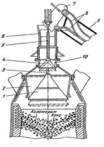
Figure 1 – Two-cone filling apparatus
The charge materials are delivered to the grate by two skips (trolleys) moving along the rails 8 of the inclined bridge 9; in the extreme upper position, the skip 7 overturns, since its front wheels roll along the rails bent down, and the rear wheels roll along other rails bent up and lifting the rear part of the skip, while a portion of the charge is poured out through the receiving funnel to the surface of the small cone, after which it descends and the material wakes up down to the surface of the large cone, and the small cone immediately rises. Similarly, two to six skips are loaded onto the surface of a large cone (they dial the feed). Then, when the small cone is raised, the large cone is lowered, and the feed material wakes up into the furnace, after which the large cone rises.
Next, a new feed is recruited to the large cone (two to six skips), but before each lowering of the small cone, it turns 60° with the funnel 10. Having loaded this feed into the furnace by lowering and lifting a large cone, the next feed is collected on it; at the same time, before each lowering of the small cone, it rotates 120 ° from the initial position with the funnel. When the following feed is set, the rotation angle is 180°, etc. Due to this rotation of the feed distributor, they do not fall into one place under the inclined bridge 9, but are relatively evenly distributed along the periphery of the grate.
During the loading process, the cones work alternately: when one is lowered, the other is raised (closed), which ensures the tightness of the furnace.
After lowering the small cone, a pressure corresponding to atmospheric pressure is created in the inter-cone space, and the large cone is under pressure of gases in the furnace, which prevents its lowering. After lowering the large cone, a pressure equal to the pressure of gases in the furnace is created in the inter-cone space, which prevents the opening of the small cone. To equalize the pressure in the inter-cone space and the furnace, clean gas is supplied to the inter-cone space at a pressure close to the pressure of gases in the furnace. This is done before lowering the large cone using equalization valves, and when lowering the small cone, the discharge valve releases gas from the interconus space into the atmosphere. The operation of the equalization valves is automated and interlocked with the operation of the cones of the filling apparatus.
The weak point of the device is the joints of cones with corresponding funnels. Here, due to the increased pressure, blast furnace gas seeps into the furnace, and the dust contained in it causes abrasive wear of the metal. Therefore, the durability of the cones is low, small; the cone is replaced almost every six months, and the large one after 1.5-2.5 g.
3.2 Blast furnace as an object of automatic control
The purpose of the design, the development of an automatic control system for the loading of a blast furnace, due to modern automation equipment based on a PLC – programmable logic controller, namely PLK63. Which allows you to increase efficiency, reliability. Replacement will lead to better functioning of the system as a whole.
Requirements for the device for automatic control of the blast furnace loading without the participation of the serviced personnel:
- regulation of the weight of the charge material 4-8 tons;
- regulation of the volume of the charge material 7300 m^3;
- remote operator control from the remote control;
- the possibility of transmitting technological information via the RS 485 protocol, as well as transmitting information about the state of the process to other PLCs;
- PLC accuracy class 0.5/0.25;
- equipment interchangeability;
- light and sound information on the operator's console;
- display of the state of the technological process and equipment on the operator's console;
- control displays on the operator console;
- prompt change of control settings;
- quick exit from an emergency situation;
- improving reliability and security;
- panel mounting housing;
- overall dimensions (HxWxD), (168x137x55) mm;
- plastic housing, with IP55 degree of protection;
Requirements for system reliability indicators are set in accordance with GOST 24. 701-86. The reliability indicators of the system should not be lower than the following values:
- for control functions - 30,000 hours of operating time for failure;
- for control functions - 30,000 hours of operating time for failure;
- for information functions - 15,000 hours
The average service life of technical means should be at least 10 years.
3.3 Analysis of existing developments on automation of blast furnace loading
Open architecture is an important characteristic of the system when integrating automated control systems into existing control systems and controls at blast furnaces. A wide range of industrial controllers of domestic and foreign production, currently used in the creation of automated control systems, in particular, blast furnaces, determines the importance of this characteristic of automated control systems.
The upper-level subsystem (operator-technologist's ARM) is developed on the basis of the TRACE MODE 5.09 SCADA system using an industrial personal computer. The mid-level subsystem (the basic level of automation) is based on the Modicon TCX Quantum PLC using distributed I/O. Distributed I/O nodes (DIOS) are integrated into a local network using Modbus Plus network technology. The lower level is the technical means of controlling electric drives and instrumentation sensors.
Communication via the Modbus Plus network of the Modicon controller with the computer of the operator– technologist station is carried out through the Factory Server of the Schneider Electric company using a network adapter installed on the computer of the operator-technologist station. The frequency-controlled drive is developed on the basis of Altivar 66 frequency converters of the Schneider Electric company
A feature of the technical structure of the automated control system is its conditional division into constant and variable parts:
- permanent part – instrumentation and control equipment and sensors that provide control of the rotary distributor itself, QC and control of the state of the RZ mechanisms; is an integral part of the automated control system;
- the variable part is the technical means ensuring synchronization of the operation of the automated control system with the upper loading system of the blast furnace and performing, if necessary, part of the functions of this system.
To solve the problem of determining the weight of the material distributed on the blast furnace grate using weighing sensors. The algorithm is based on the control of energy costs during the distribution of the material, as well as on the control of changes in the kinetic energy reserve during its unloading. The results of the automated control system implementation at the facility confirmed the satisfactory accuracy of this method when implementing various modes of material distribution in accordance with the specified loading program. The coefficients of the equations of the distribution algorithm are adapted from feed to feed, which eliminates the effect of accumulation of errors in its computational part.
The automated control system allows the operator, using a functional keyboard, to remotely call control functions during the technological process, including changing tasks for the current process parameters, and also displays the technological loading process in the form of mnemonic diagrams of technological nodes and mechanisms, graphs of parameter changes and their settings to communicate the operator–technologist with the loading process. The developed process visualization package provides prompt and representative reading of information from the screens of the ARM monitor.
The Trace Mode tool system, as you know, includes two editors:
- channel database editor;
- data representation editor.
In the channel database editor, the configuration of the operator station used in the automated control system is described, communication channels with the PLC connected to them are configured, variables and methods of their processing are set, menus for calling information and management are created, reports are generated, a list of variables, etc. The operator station (OS) of the ARM supports operation via the Modbus Plus network with a mid–level PLC - Modicon TCX Quantum.
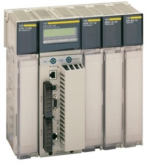
Figure 2 – Appearance of the Modicon TCX Quantum software controller
An ARM node using a 1024-channel instrumentation system without auto-construction and two objects. One of the objects is a set of channels that determine the number of technological variables (analog and discrete) used in the automated control system, the other includes channels used to implement the operator-technologist's own interface functions, including the visualization level.
The channels provide primary and output data processing. All other data processing and management tasks are developed as separate programs. For this purpose, two programming languages are provided in the IEC-61131 standard: Techno FBD and Techno IL. Programs created in the FBD language can be called from channel routines.
The number of input/output signals of the automated control system reaches 160.
In fact, in the system, the number of channels used for technological variables and the implementation of the operator's own interface functions is significantly more than stated by the instrumental system, i.e. 1024. The use of global variables defined in the Trace Mode made it possible to effectively solve the problem of designing a top-level subsystem based on an instrumental system with 1024 inputs/outputs.
The use of global variables was particularly effective in the off-line operation of the system during the formation of blast furnace loading cycles. In this case, the total loading cycle is set by the operator for twenty feeds (maximum), each of which consists of six skips of different material.
In total, about 1250 channels have been created in the project, of which 310 are connected to the OPC server. The automated control system uses OPC Factory Server developed by Schneider Electric with local access. In this application, the OPC client and the OPC server are installed on the same station, i.e. on the ARM computer.
It is necessary to note the effectiveness of programming some tasks in the FBD language, which was used to create additional controls and visualization and, most importantly, to improve the dynamics of displaying messages on the technological screens of the operator-technologist interface. As you know, in TRACE MODE, messages are generated by encoding state words without using symbolic variables. In the presence of a large number of messages, taking into account the delay in processing and converting signals by the OPC channel, the delay in displaying messages on the technological screen becomes unacceptably large, which can lead to the visual loss of important technological information.
In the automated control system, in order to reduce the delay time of displaying messages on FBD blocks, a program for processing state words using the logarithm block of the state word has been developed. In this case, the change of the state word relative to the previous cycle of its reading is checked beforehand. This approach made it possible to significantly reduce the delay time of displaying messages on technological screens during the technological loading process.
The main requirement for the organization of the visualization level structure during the operation of the ROM was the promptness of the transition to the called technological screen. TRACE MODE tools made it possible to create a convenient system of technological screens, which are previously combined into functional groups, within which subgroups are formed, organized into auxiliary screens.
Access to any functional group is carried out through the main screen "MNEMONIC DIAGRAM" Figure 3. Then, using the appropriate buttons, access to auxiliary screens is carried out.
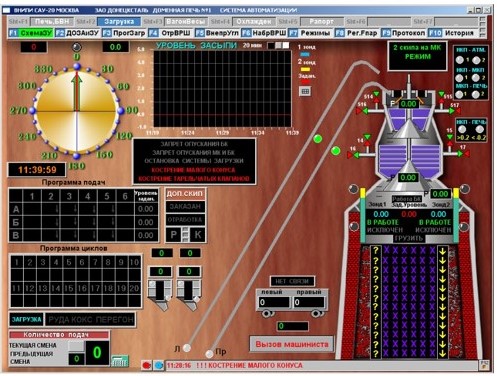
Figure 3 – On-screen form of the loading mnemonic
Provides prompt access to the main screens using keyboard hotkeys. The technological screen is divided into working and information zones. The information zone is located at the top of the screen and contains:
- name of the screen;
- date and time of system activation;
- a message string that indicates the technological state of the variable, the type of mechanism and its mode of operation;
- date and time when the message was generated for this variable;
- the button to view the alarm report;
- the button for viewing the graphical display of the variable.
"Operation" mode is the mode of operation in which the control and management functions of the automated control system are carried out in real time. At the same time, the system performs:
- "tracking" the state of the mechanisms of the upper loading of the blast furnace, taking into account the necessary sequence of the mechanisms.
- processes information and generates control signals based on data received from sensors of the technological process and the technical condition of the main components of the ROM;
- calculates and transmits control signals to the electric drive of the rotary distributor in accordance with the specified algorithm for the distribution of charge material on the blast furnace grate.
In the process of unloading the charge material, the mid-level subsystem calculates the amount of material entering the grate per unit of time.
In the "Work" mode, archiving and formation of protocols are carried out. TRACE MODE's archiving and alarm report generation capabilities are fully used here. The data in the archive is updated cyclically. The data in the alarm report is entered as separate lines, each of which contains the time and date of its formation. Additionally, each line indicates the type of messages: emergency, technological, warning or system, determining the status of the automated control system.
The automated control system provides "hot" redundancy of the central processor module (CPU) 140 CPU 213 04 of the control controller. The CPU modules (main and backup) are located in the controller cabinet on separate slots and are connected to the modules of the system nodes by the Modbus Plus (MB+) LAN. The software of the main and backup CPUs are almost identical and differ only in the software modules MAIN and RESERVA, which determine the status of the CPU: main – MAIN, backup – RESERVA. The CPU status is determined during system configuration.
When implementing redundancy, a feature of the local MB+ network is used, which is a peer-to-peer network with serial transmission of a network token to remote nodes of the system and the ability to use Active X applications in TRACE MODE.
The "backup" CPU is constantly in the process of reading information about the state of the I/O modules of the system when the network token is "captured", i.e. it works the same way as the main CPU, and also generates control output signals. However, when the "main" CPU is running, the control signals of the "backup" are disconnected from the communication lines, both from the OS and from the distributed I/O nodes. When a malfunction of the "main" CPU is detected, the "backup" CPU has full information about the state of the technological process and automatically connects to the control process, while disabling the faulty CPU. The switching time is no more than 2 seconds, which is quite acceptable for the technological process of loading a blast furnace.
3.4 Justification of the direction of automation of blast furnace loading
The main problem that exists at the Donetsk metalurgich plant is the use of outdated equipment. PLC Schneider Electric, Siemens etc. Use carries the risk of gradual failure, the inability to find a similar replacement. Therefore, to build an automation system, a PLC is needed, which can be easily found on the market and for the possibility of buying a reserve for quick switching between them. Also, the choice of a PLC as a control unit is based on a large number of parameters and modularity, the control and regulation nodes of a PLC based on a central processor have the necessary computing power and cope with system automation.
The parameter that is responsible for loading the blast furnace that can be automated is the regulation of the charge material consumption.
The filling apparatus consists of two cones: large and small. When lowering materials from a small cone, air enters the inter-cone space.
Before lowering the small cone, the charge level is measured with the help of a level gauge.
To increase the reliability of the system, dual equalizer signaling devices are used, the constants of which are switched on sequentially. This complication is due to the possibility of bending the rods of cones.
3.5 Algorithmization of operation and circuit solutions of the blast furnace automatic loading control system
The automatic control system for loading the blast furnace includes a programmable logic controller PLK63 from ARIES, which interacts with sensors, receives information from the control object, processes it in accordance with the embedded algorithm and provides control of the impact on the actuators.
The use of microprocessor tools for the implementation of a subsystem of technological protections and protective locks gives the following advantages:
- the possibility of continuous monitoring of the reliability of all input information with alarm and fault registration of individual sensors or communication channels;
- restructuring of algorithms when detecting malfunctions;
- control of the execution of commands in fact and time;
- authorized control of any sensor and algorithm;
- the possibility of making operational and non-operational changes with authorized access to changes simultaneously automatically registering the fact of access and making changes;
- fixing the time of occurrence of registration events;
- automatic preparation of accounting documentation;
- high maintainability of technical means;
- reduction of overall dimensions of technical means;
ARIES PLK63 is a controller with HMI for local automation tools in a busbar design. The PLC itself is shown in Figure 4 has 8 analog inputs for connecting sensors and 6 outputs. The number of discrete outputs is 8. The supply voltage of the discrete output is 24 ± 3 V. It is programmed through the CODESYS V2 program via the KS1, RS-485, RS-232 interface. The advantages include the possibility of expansion by connecting I/O modules. Increasing the digital outputs by connecting the ARIES MP1 module. The case has a convenient mounting on a DIN rail. Built-in secondary power supply output voltage 24 ± 3 V current no more than 180 mA, allows you to work for some time in case of power outages, as well as the execution of the program to transfer the output elements to a safe state.
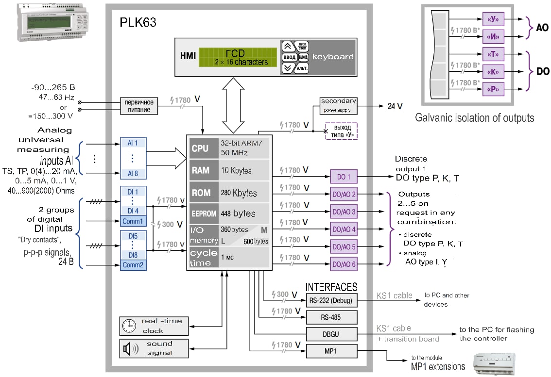
Figure 4 – Functional diagram of the PLC 63
Interaction with sensors and actuators is determined by appropriate exchange protocols that take into account the features of the functioning of the system as a whole and the requirements of hardware and software and schematic compatibility with other devices and systems.
The block diagram shows all the main functional parts of the product (elements, devices and functional groups) and the main relationships between them. The graphical construction of the scheme provides the best representation of the sequence of interaction of functional parts in the system. On the relationship line, arrows indicate the direction of the processes occurring in the device.
This system includes the following blocks:
- D1 – the volume of the charge above the small cone;
- D2 - the volume of the charge above the large cone;
- BP1 - power supply unit;
- PLC;
- PBR - contactless reversible starter;
- MEO - executive electric single-turn mechanism;
- UP - position indicator;
- RS-485 - industrial network standard;
- PC - personal computer;
- DP - control room.
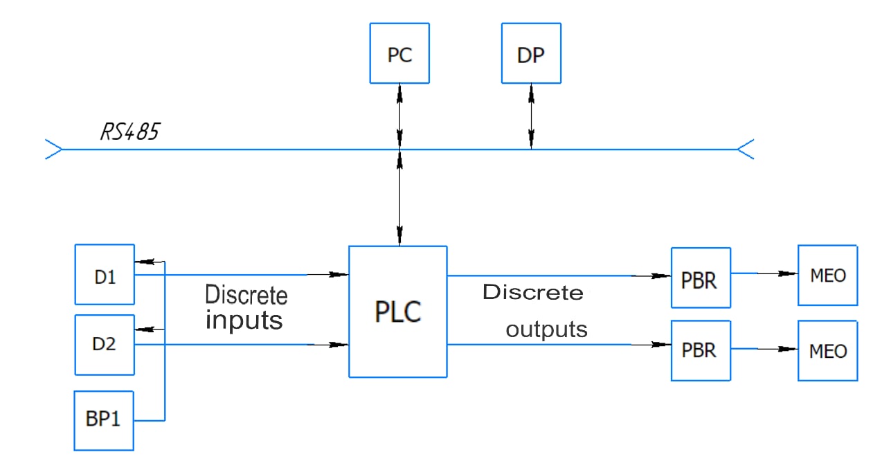
Figure 5 – Block diagram of blast furnace loading control
The main principle of the automatic load control system is the use of PLC computing power. That will allow you to rationally manage the charge volume in the device.
The preliminary stage of the signal comes from the sensor ULM-11A1, which signals the volume of the charge in the grate space above the small cone. The parameters of the charge volume are calculated by the PLC and compared between the two sensors.
During the loading process, the cones work alternately: when one is lowered, the other is raised (closed), which ensures the tightness of the furnace.
After lowering the small cone, a pressure corresponding to atmospheric pressure is created in the inter-cone space, and the large cone is under the pressure of gases in the furnace, which prevents its lowering. After lowering the large cone, a pressure equal to the pressure of gases in the furnace is created in the inter-cone space, which prevents the opening of the small cone.
The weak point of the device is the joints of cones with corresponding funnels. Here, due to the increased pressure, blast furnace gas seeps into the furnace, and the dust contained in it causes abrasive wear of the metal. Therefore, the durability of the cones is low, small; the cone is replaced almost every six months, and the large one after 1.5-2.5 g. The electric actuating mechanism MEO-1600 is used for opening and closing cones on blast furnaces.
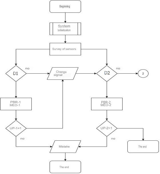
Figure 6 – Block diagram of the algorithm of the automatic control system of the blast furnace loading
The basic electrical circuit of automation is used to depict the mutual electrical connection of devices and devices, the actions of which provide solutions to the problems of automatic control, signaling and process control. The basic electrical circuit of automatic control, regulation, signaling and power supply must be performed in a detailed manner in accordance with the requirements of the ESKD standards (unified system of design documentation) according to the rules of execution of circuits, conditional graphic designation, marking of circuits and alphanumeric designations of circuit elements according to the corresponding GOST 21404 - 85, etc.
The electrical circuit of the automatic control system for loading the blast furnace in an expanded manner has been developed, where it is shown on sheet 3 of the graphic part of the diploma project.
Charge loading control is performed by the ULM-11A1 level gauge operating on the principle of an FMCW radar. This is one of the classical methods of non-contact distance measurement, which minimizes the influence of parasitic interference and interference associated with irregularities (disturbances) of the surface of the measured product. The occurrence of a signal via pulse lines is transmitted to a sensor of the type "ULM-11A1" (pos. 5P1, 5P2) with microprocessor processing.
The ULM-11A1 contactless radar level gauge is focused on solving general technological problems of level measurement in various tanks with liquid products and bulk materials.
The ULM-11A1 level gauge sensors use microprocessors, so the sensors are intelligent. Microprocessors give sensors a number of advantages: configuration and change of the measuring range, regular compensation of environmental influences, improved operation, remote control of the sensor, remote receipt of diagnostic information. These advantages quickly recoup the costs.
ULM-11A1 pressure sensors have 0.50%, 0.25%, 0.15% and 1.5% accuracy classes.
The ULM-11A1 pressure sensors are powered from the Karat-22 power supply (pos. B1) voltage 24 V DC. The output current of the ULM-11A1 signal is 4-20ma, proportionally to control the level of the charge material, the signal goes to the corresponding outputs of the PLK63 software controller from the ARIES company (pos. A1). The software controller is powered by AC 220V.
The output current signals of 4-20 Ma, in proportion to the consumption of the blast furnace, are supplied to the corresponding inputs of the programmable controller type PLK63 from the company ARIES (pos. Al). The ULM-11A1 sensors for measuring charge flow (pos. 5P1) output two analog signals (P-7, P-8) going to the PLC input, namely (AI1, AI2). ULM-11A1 sensors for measuring the charge flow in the grate (pos. 5P2) output two analog signals (P-9, P-10) going to the PLC input, namely (AI3, AI4). The programmable controller of the PLK63 type is powered from an AC network with a voltage of 220 V.
In this system, we use direct digital control based on the PLK63 controller from the ARIES company. It is a top-class programmable logic controller designed to solve complex automation tasks of technological processes, and can be used in almost all industries. The controller has 8 analog inputs with the designation (AII, AI2, AI3, AI4, IFS, AI6. I7. AI8) and exactly the same number of discrete (DI1, DI2, DI3, DI4, DI5, DI6, DI7, DI8). The number of outputs inside the controller is 6. The number of discrete outputs is 1 (DO1). The number of analog outputs is 4 (AO1, AO2, AO3, AO4, AO45) the CPU is 32-bit, RISC 50 MHz based on the ARM7 core. The size of the Retain memory (EEPROM) is 448 bytes. The amount of RAM for storing program variables is 10 kb. The amount of program storage memory is 280 kb. The amount of I/O memory is 600 bytes.
On the case there are elements of a human-machine interface, a text monochrome LCD display with backlight the number of familiar (characters) 2 x 16. There are 6 control buttons on the front panel: "Start/Stop", "Exit", "Alt", "Input", "Up", "Down". The controller has the following important functions and characteristics:
- very high performance;
- multiprocessor mode of operation;
- diagnostic functions and diagnostic buffer:
- built-in functions for display (control);
- software parameterized modules;
- operation without forced ventilation is possible;
- high resistance to vibration;
- clock functions, working time counter, data copying;
- error handling;
- built-in interface suitable for simple network solutions.
PLK63 is a software logic controller of the highest quality class for solving complex tasks of automation of technical processes. The main areas of application of ARIES PLK63 are housing and communal services, TSTP, etc., boiler houses, small installations.
To change the level of the charge material in the controller in accordance with the algorithm, the calculation of the controlling influences for the regulation law takes place. Control actions of the discrete signal output module MP1 (pos. A2) to the controller via a contactless reversible starter of the PBR-3A type (pos. 2P7, 3P7, 4P7, 5P7).
The input signal of the starters is a voltage of negative polarity applied relative to pin 8 to input "M" (pin 7) or input "B" (pin 9). The designation "M" (less) or "B" (more) is assumed conditionally.
To control the starter with the help of keys, the starter has a voltage source, the positive potential of which is output to terminal 8, the negative potential is output to terminal 10.
Using the keys, pin 10 is connected to the input "M" or "B".
In the initial state (there are no input signals), the voltage on the emitter V17 is less than the switching voltage due to the small resistance value of the resistors R7, R20, which reduce the voltage on the emitter through the positive terminal of the diode bridge V33...V36.
In this regard, transistors V13 and V14 are closed, there are no control pulses on transformers T2 and T3. Triacs V4...V7 are closed. There is no output voltage.
When the control voltage is applied to terminals 8-7 (8-9), the capacitors C1 (C2) and C3 are charged, which perform the functions of filters and elements of the reverse delay circuit. The flow of current through the resistors R7, R20, the negative terminal of the diode bridge V33...V36 and the diode V10 (V11) leads to an increase in the voltage drop on the resistors R7 and R20 and the opening of the diode of the negative terminal of the diode bridge V33...V36. As a result, the voltage decreases on the basis of the transistor V13 (V14), the capacitors C3 and C7 are charged and the voltage increases on the basis of the transistor V14 (V13) and the emitter of the transistor V17 relative to the base 1 of the transistor V17.
When the voltage on the emitter of the transistor V17 reaches the switching voltage, the transistor opens and the capacitor C7 is discharged along the circuit: resistor R10, the base-emitter junction of the transistor V14 (V13), diode V16 (V15), the emitter-base junction of the transistor V17 and the negative terminal of the diode bridge V33...V36.
The capacitor discharge current flowing through the base of the transistor V14 (V13) is amplified by it and a pulse is formed in the transformer T2 (T3), unlocking triacs V4 (V5) and V7 (V6). The charge-discharge process of the capacitor C7 is repeated periodically and stops only after removing the input signal. Triacs V4 (V5) and V7 (V6) are also open until the input voltage is removed. The triacs of the power circuit serve to supply voltage to the electric motor.
Capacitor C4 and resistors R8, R9 are designed to improve the switching conditions of triacs.
The starter is protected from simultaneous unlocking of all triacs caused by the supply of voltage to both inputs, or a rapid reversal of the control voltage.
The starter contains varistors R32...R35 to protect triacs from overvoltage when switching synchronous motors.
The PBR-3A starters contain an overload protection circuit for the electric motor. The protection circuit ensures that the electric motor of the mechanism is switched off when the output organ of the mechanism exits at the stop or when it is jammed in an intermediate position.
The input signal of the protection circuit is the current of the electric motor.
The output voltage of current transformers T4 and T5 through diodes V41...V44, resistor R22 is supplied to capacitor C11. If the capacitor is charged to the unlocking voltage of transistor V25, the transistor will open, the emitter potential of transistor V22 will decrease (at an almost constant voltage based on this transistor).
Transistor V22 will open and bypass the power supply circuit of the emitter of transistor V17, pulse generation will stop. In this position, the circuit remains until the input voltage is removed from the starter input.
The starter is designed to connect electric motors of various capacities, therefore, a change in the protection actuation current is provided by changing the position of the motor of the potentiometer R29 located on the front panel of the starter.
Single-turn electric actuators of the MEO-1600 type consist of the following main parts: gearbox, three-phase electric motor, current sensor blocks, electromagnetic brake. The principle of operation of the mechanisms is based on the termination of the electrical signal received from the starters in a rotational alternation.
The gearbox is the main unit of the mechanism on which the components of the mechanism are installed.
The gearbox consists of a housing, cylindrical straight-toothed steps, a manual drive, and a brake.
The manual drive is used to move the output shaft (regulating body) during the installation and adjustment of mechanisms, as well as in emergency situations (lack of supply voltage).
The movement of the output shaft of the mechanisms is carried out by rotating the flywheel of the manual drive. The presence of a planetary gear in the gearbox of the mechanisms allows the use of a manual drive regardless of whether the electric motor is turned on or off.
Asynchronous three-phase electric motors are installed on the mechanisms. The actuator uses a block of current sensors of the BSPT-10 type, the output signal from which 4-20mA goes to the digital position indicators of the MTM-310 type (pos. 2P9, 3P9, 4P9, 5P9) to the PLC output (pos. P11, P12, P13, P14) thereby signals how much is open now the cone. The mechanism uses BSPT-10 sensor blocks, which consist of two current displacement sensors, a profile cam, four microswitches, four shaft microswitch cams. All elements are fixed on the sensor side housing
A mechanical brake is provided in the mechanism to limit the output shaft run-out and prevent its movement from the efforts of the regulatory body in the absence of voltage on the electric motor.
The actuating mechanism for controlling the closure of the cone until it becomes equal to the set value.
The operation of the digital position indicator is based on the analog-to-digital conversion of the values indicated on the digital indicator by a person in accordance with the value of the output current.
The digital pointer is powered from a voltage of 24 V DC with the help of a group power supply unit MTM-140 (pos. B2).
Conclusions
The master's thesis is devoted to an urgent scientific task is to increase the efficiency of the high-quality technological process of loading the blast furnace grate device by developing an automatic control system, as well as monitoring and regulating the main technological parameters of this control object. Within the framework of the conducted research, the following was performed:
- Analysis of the technological process of loading the blast furnace grate device as an automation object;
- The blast furnace is considered as an object of automatic control;
- Analysis of existing developments on blast furnace automation;
- The directions of automation of the blast furnace are substantiated;
- A structural control scheme, a functional automation scheme, as well as algorithms of the blast furnace technological process have been developed.
When writing this abstract, the master's work has not yet been completed. Final completion: June 2023. The full text of the work and materials on the topic can be obtained from the author or his supervisor after the specified date.
List of sources
- Automation of basic metallurgical processes. Lipukhin Yu.V., Bulatov Yu.I., Bok G., Knorr M.M.: Metallurgy, 1990. 280 p.
- Kharakhnin K.A., Bulatov Yu.I., Mochlain V.N. Automation of blast furnace production: Studies. Stipend. – Cherepovets: GOU VPO ChSU, 2015. – 70s.
- Electrical equipment of blast furnace shops. Agronik S.G., Vlatt M.Yu., Skrylnikov S.V., Moscow "Metallurgy", 1966. 196 p.
- Kotov K. I., Shershever M. A. Means of measurement, control and automation of technological processes. – M.: Metallurgy, 1987. – 496 p.
- Gromakov E. I. Design of automated systems: an educational and methodical manual. – Tomsk: Tomsk Polytechnic University, 2010. – 173 p.
- Glinkov, G.M. Automated process control systems in ferrous metallurgy: textbook for universities. / G.M. Glinkov, V.A. Makovsky – 2nd ed., reprint. and additional – M.: "Metallurgy", 1999. – 310 p.
- Official website of Donetsk Metallurgical Plant [Electronic resource]: Access mode: http://dmz.donetsksteel.com/ru/company (Date of collapse 25.05.2021)
- Domain production [Electronic resource]: Access mode: https://metalspace.ru/education-career/osnovy-metallurgii/domennaya-pech/810-domennoe-proizvodstvo.html (Date of collapse 25.05.2021).
- Kisarimov, R.A. Electric drive: handbook. / R.A. Kisarimov, Moscow, IP RadioSoft, 2008.- 391 p.
- Wakerly D. Designing digital devices / D. Wakerly. – M.: Postmarket, 2002. – Volume 2. – 528 p.