Eugene A. Astahov
Faculty: Computer Science
Speciality: System Programming
Theme of master's diploma:
Research and Development of FPGA project verification method using Guide Probe methodology on the base of Boundary Scan technology
Scientific supervisor: Yuri E. Zinchenko
Introduction
As is known process of designing of computers is accompanied by debugging (verification) at all design stages. Verification of modern difficult devices on statistican occupies 75-80 % from common time of designing and with the tendency to deterioration of this parametre. Especially the verification acute problem costs at a hardware level (intracircuit verification). I.e. when the project is omitted in the target device (a LSI, GSI), therefore an operation theme routed on development of methods and resources of verification of projects, Shipped in the is programmed-logic chip (COTTON VELVET, FPGA), is actual. Fundamental technological basis for an offered way of verification is the technology of "boundary scanning» (Boundary Scan - BS).
Developed initially on purpose контролепригодного designing and LSI diagnostics, this technology has found also application at programming and verification modern COTTON VELVET. As a whole technology BS provides access to internal points of a LSI through specially organised port JTAG (Joint Test Advanced Group), However it does not give the answer to how to test a chip or to verify the project which is in it. For the answer to this question in the given operation it is offered to use methodology зондовой diagnostics, applied to traditional digital devices. Sharing of technology BS and methodology зондовой diagnostics (ЗД) digital devices (ЦУ) Allows to provide access for the purpose of the analysis to internal breakpoints of the project in a target chip, Defined by algorithm of sounding.
Probe diagnostics was very popular in the 80's. In the 90 years, with the growing popularity of FPGA-based circuits in buildings such as BGA, drastically limited access to contacts circuits, because the chip contacts are located very close to each other, makes it difficult to use the traditional method of probe diagnostics using the probe. Therefore probe diagnostics is rapidly losing its position. Projects are now being dropped in the FPGA, and Boundary Scan technology provides access to internal points scheme that allows you to return to the ideas of probe diagnostics of a new quality-chip level.
This work aims to develop algorithms for verification by the adaptation and improvement of algorithms and approaches probe diagnostics.
Subject of study is an algorithm for verification of projects loaded in the FPGA-based adaptation methods, ideas and approaches probe diagnostics.
Purpose and objectives of the study. The purpose of work is to develop efficient algorithms for verification of projects that provide a quick way to search for possible errors with minimal time finding and fixing bugs with the greatest possible degree of localization.
To achieve this goal in the following objectives:
1. Adaptation of the basic algorithm SCAN troubleshooting method slave probe for verification of projects described in the structural type of HDL.
2. Development of software and hardware verification of FPGA project methodology driven probe.
3. An experimental study of algorithms and structures projects FPGA verification methodology driven probe.
The browse of researches and developments on a theme «Research and Development of FPGA project verification method using Guide Probe methodology on the base of Boundary Scan technology»
Regional level:
DonNTU master's Materials
1. http://masters.donntu.ru/2002/fvti/miroshnikov/diss/index.htm
«Разработка алгоритмов тестирования FPGA-устройств по технологии переферийного сканирования»
Author: Мирошников Александр Сергеевич
Scientific supervisor: к.т.н., доцент каф. ЭВМ ДонНТУ Зинченко Ю.Е.
2. http://masters.donntu.ru/2008/fvti/svistunov/diss/index.html
«Исследование и разработка на FPGA SPP-архитектуры поста контроля цифровых устройств»
Author: Cвистунов Сергей Николаевич
Scientific supervisor: к.т.н., доцент каф. ЭВМ ДонНТУ Зинченко Ю.Е.
3. http://masters.donntu.ru/2006/fvti/bobrovskyy/diss/index.htm
«Разработка структуры поста контроля зондовой диагностики ТЭЗ на базе HDL- и FPGA-технологий»
Author: Бобровский Константин Викторович
Scientific supervisor: к.т.н., доцент каф. ЭВМ ДонНТУ Зинченко Ю.Е.
4. http://masters.donntu.ru/2006/fvti/myadelets/diss/index.htm
«Разработка и исследование метода синтеза тестов для типовых элементов замены (ТЭЗ)»
Author: Мяделец Александр Александрович
Scientific supervisor: к.т.н., доцент каф. ЭВМ ДонНТУ Зинченко Ю.Е.
5. http://masters.donntu.ru/2002/fvti/rytov/dissert.htm
«Разработка диагностической модели FPGA - устройств и синтез тестов на ее основе»
Author: Рытов Александр Сергеевич
Scientific supervisor: к.т.н., доцент каф. ЭВМ ДонНТУ Зинченко Ю.Е.
6. http://masters.donntu.ru/2005/fvti/mukha/diss/index.htm
«Исследование реализаций MPEG2 видеопроцессоров на FPGA и PRUS»
Author: Муха Евгений Михайлович
Scientific supervisor: к.т.н., доцент каф. ЭВМ ДонНТУ Зинченко Ю.Е.
7. http://masters.donntu.ru/2004/fvti/korchenko/diss/index.htm
«Розробка способів рішення HDL-задач і системи тестування знань на їх основі»
Author: Корченко Александр Александрович
Scientific supervisor: к.т.н., доцент каф. ЭВМ ДонНТУ Зинченко Ю.Е.
National level:
At this level of operation in the field of a theme магистерской operations are presented by operations of my supervisor of studies. On this link http://hardclub.donntu.ru/zinchenko/science.htm It is possible to learn about scientific developments at the given stage.
Global level:
In the world in the given problem are engaged much more intensively.
On a site IEEE Xplore contains big количесвто scientific articles, including on the given subjects. However in an easy approach only short browses and outputs of articles are presented, And the main maintenance well only to the registered users.
In this article, http://www.soccentral.com/PrintPage.asp?PassedEntryID=13186 structurally described ideas in the direction that the industry is developing today. This approach is relevant.
Now there are no similar program implementations of the given method of diagnostics assumed by a theme магистерской of operation Or, at least, they are in the closed access.
The main maintenance of operation
In a figure 1 animation of existing search algorithms for faults is resulted.

Figure 1 — Search algorithms for faults (animation, 17 frames, 3 cycles, 146 Kbytes).
As is known, there are some algorithms ЗД, such as algorithm of consecutive sounding (Scan), Algorithm of half division (Galop) and combined algorithm (Galop + Scan), grounded on a combination of first two algorithms. All these algorithms can be applied and in case of intracircuit verification.
It includes standard software of Xilinx corporation and special ON зондового the diagnosings, developed by the author of operation. Standard resources are constructed on ChipScope - subsystem BS of Xilinx corporation. Here following components enter:
1. Core Generator - generator IP of kernels ICON, ILA and others which realise mechanisms BS - is used for creation of a BSDL-deckhouse of the project by implantation IP of kernels in an initial code of the project of the user before a synthesis stage.
2. Core Inserter - linker IP of kernels - is used for alternative construction of a BSDL-superstructure of the project which takes root into the initial project of the user after its synthesis.
3. Core Analyzer - analyzer IP of kernels - is used as an auxiliary resource for the visual analysis of test responses in internal breakpoints of the project shipped in COTTON VELVET.
We stipulates develop and compare several structures of software systems verification of design, to identify the strengths and weaknesses each technical solution, to draw conclusions about the best structure for its implementation.
Figure 2 shows a system of verification of FPGA-projects with built-sensing algorithm
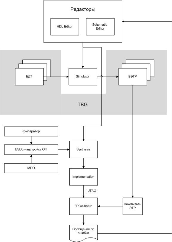
Figure 2 — System Verification FPGA-projects with built-sensing algorithm
description of the structure:
The work begins with the creation of the project to editors:
1. HDL Editor - Create a software package in a structural HDL-style
2. Schematic Editor - creation scheme in graphical form, using a ready-made library component
Then your project to debug the deletion of the simple logic errors. For this project, created in the editors referred to the block Simulator, which is run through a set of tests, which provides a block TBG - Test Bench Generator.
This block contains the TBG in its recruiting database tests (RDTs), which is tested your project. As well as the base standard test reactions (BETR) - the results of testing the project in the block Simulator. To create a database of tests may be used for PRTG, developed by the Donetsk State Technical University on faculty computers. The test suite can be created manually based on the specifications of the project.
After debugging the project is passed to block Synthesis. At this stage, the project connects BSDL-superstructure design object (BSDL - Boundary Scan Description Language), which consists of:
1. comparator - a block that performs a comparison of the control points (CT) with base benchmark reactions (BETR), which is received in block TBG.
2. MPO - Module troubleshooting, in the form of BSDL.
Both of these blocks in the form of BSDL-superstructure connected to the project at the stage of Synthesis.
Next project is going through Implementation, which involves the stage of creating the model. The output of block Implementation obtain bitstream, consisting from the original project and BSDL-superstructure containing the search module errors.
Using cable JTAG, bitstream immersed for Evaluation Boards FPGA (FPGA-board), such as Altera DE2 board. This motherboard via an external connector (eg USB) connected to the drive reference test reactions (drive Etruscan), information on which is recorded on the PC, using data base of standard test reactions (BETR).
After the start of the debug FPGA-board, algorithms for finding bugs, implemented as a module troubleshooting BSDL-add-in will begin their work.
They will perform sensing. In accordance with the algorithm to escape first control point (CT), reads the test reaction is compared with the standard which is selected from a database of standard test reactions (BETR). It is the time of first mismatch. Depending on this decision: correct response or incorrect. Then select the next control point (CT) or another CT.
The algorithm continues until until it finds a component that will fail. On display will get a message to the identification of the components that will provide information for the designer to fix the source code.
Advantages structure described above are:
1. Reducing traffic transmitted information about the values of the control points (CT) between the FPGA and PC, because This information is processed in the FPGA.
2. Quick access to the control points (CT) without the need for external interaction.
Figure 3 shows a verification system FPGA-based projects GTO
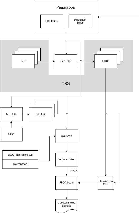
Figure 3 — The system of verification of FPGA-based projects GTO
In this structure, added to block construction of the module graph search errors (MP MPO). This block receives information from a block TBG and uses the search module error (MPO) to form a database graph search errors (DB MPO), which then written to the drive Etruscan.
At the preliminary stage constructed database graph search errors (DB MPO).
This structure is favorably the fact that in BSDL-add not implemented the search module error (MPO) and embedded comparator works with the database GTO sold for a horizontal format, regardless of of the search algorithm errors.
The remaining steps are similar to the previous structure.
Advantages of this structure are:
1. To implement a new algorithm for finding bugs in the system software, need to rewrite only the power supply module for constructing a graph search of errors.
2. Reducing traffic transmitted information about the values of the control points (CT) between the FPGA and PC, because This information is processed in the FPGA.
3. Quick access to the control points (CT) without the need for external interaction.
Figure 4 shows the system of verification of FPGA-projects with external sensing algorithm
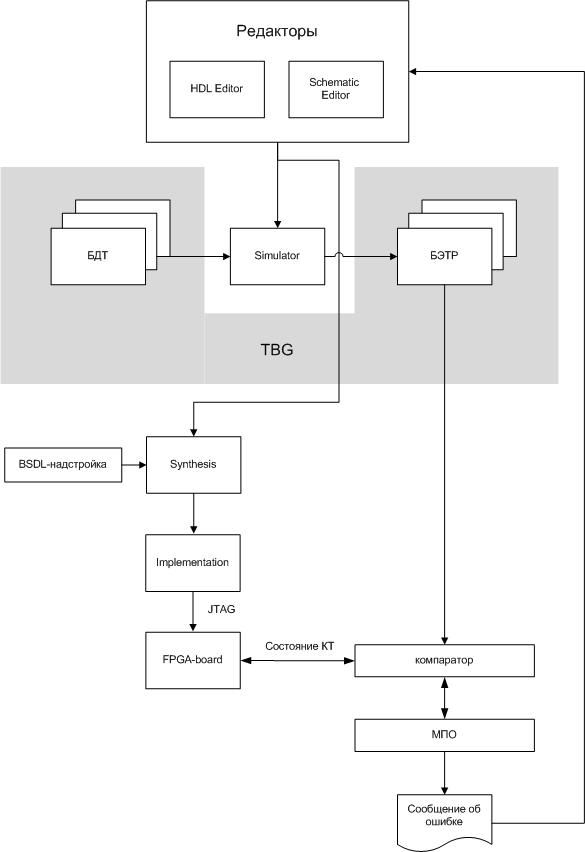
Figure 4 — System Verification FPGA-projects with external sensing algorithm
The purpose of this structure is the ultimate simplification of BSDL-add, because placed on it only function seizures checkpoint (CT) identified from the outside. All other functions implemented in PС: search error comparator.
However, the implementation of such an approach requires an increase in traffic between FPGA and PC, which is critical for large projects, because in the process search module errors made inquiries of CT.
The whole arsenal of systems for probe diagnostics (GS) can be easily adapted for verification.
Advantages of this structure are:
1. Many already implemented algorithms for probe diagnostics, adaptation may used to detect errors in the project, sunk to the FPGA. The role of the probe performs technology Boundary Scan, providing access to internal points of the project, provides support BSDL-superstructure.
2. Simple BSDL-add
3. Traditional algorithms for probe diagnostics can be applied both to the SRE, and for verification of errors ie You can use the system AutoProbe fault diagnosis SRE developed in DonNTU, to verify the error.
Disadvantages of this structure are:
1. Intensive traffic between the FPGA-board instrumentation and PC, which can play a significant negative role for large projects.
Conclusions
We obtain the following results:
1. Proposed three structures verification system software based on the idea of probe diagnostics (GS) fault and made their comparative analysis.
2. The optimum structure of the verification and set tasks for software development.
References
1. Барашко А.С., Скобцов Ю.А., Сперанский Д.В. Моделирование и тестирование дискретных устройств. — К., Наукова думка, 1992 — c. 28-32.
2. Беннетс Р. Проектирование тестопригодных логических схем. — Пер. с английского. — М.: Радио и связь, 1990 — 176 с.
3. Тарасенко А.Н. Методы оценки и показатели тестируемости дискретных устройств (обзор) // Зарубежная радиоэлектроника, 1989, выпуск 7 — с. 24-29.
4. Зинченко Ю.Е. T—модель дискретного устройства и решение диагностических задач на ее основе. — Электронная библиотека магистра Маркитанова В.Р.
http://www.masters.donntu.ru/2001/fvti/markitantov/diss/library/zinchenko1/index.html, Портал магистров, 2001.
5. Уильямс Т.У., Паркер К.И. Проектирование контролепригодных устройств // ТИИЭР, 1983 — с. 122-139.
6. Техническая диагностика цифровых и микропроцессорных структур: учебник // В.И. Хаханов.— K.: ИСИО, 1995 — 242с.
7. Горяшко А.П. Синтез диагностируемых схем вычислительных устройств. М.: Наука., 1987. – 288 с.
8. Agrawal V.D. Essentials of electronic testing for digital, memory and mixed-signal VLSI circuits. Kluwer Academic Publishers, 2000, — 690c.
9. Автоматизация диагностирования электронных устройств // Ю.В. Малышко, В.П. Чипулис, С.Г. Шаршунов. — М.: Энергоатомиздат, 1986. — 216 с.
10. Соловьев В.В. Проектирование цифровых схем на основе ПЛИС. — М.:Горячая линия-Телеком, 2001. 636с. ил.
11. Ярмолик В.Н. Контроль и диагностика цифровых узлов ЭВМ. — Мн.: Наука и техника. 1988, — 240 с.
12. Давыдов П.С. Техническая диагностика радиоэлектронных устройств и систем. — М.: Радио и связь, 1988. — 256 с.