
Master work
GENERAL WORK DESCRIPTION
Urgency. There is automation of processes in all spheres of knowledge over the around world. In some applications, the automation is limited to the software creation for PC, but in most cases it is required the creation of specialized computers. To organize PC need a managing automat as one of the components. Its functions include the control signals generation, based on some algorithm for the operating parts of a computer.
The managing automat effectiveness in many ways defines the characteristics of the system as a whole. Algorithm for management of the system is given by a controlling code, which goes to the managing automat from the external environment. Algorithm for management of managing automat is called firmware and is being implemented by managing automat. One of the main problems during creating a specialized computer is finding a compromise between speed, cost and universality of managing automat. Also time of design and scheme implementation of managing automat is crucial.
As is known, managing automats with a rigid logic gain performance compared with managing automats with programmed logic, but they have a rigid structure and cannot be modified. EPLD permit to replace a device configured for the chip. Thus, it is possible to create reprogrammable managing automat with a rigid logic [1].
State machine is the most common mathematical model of digital device or digital system. It is therefore crucial for the development of various digital devices and systems to use effective methods of state machines synthesis. At the same time, realized in the known packages of automation design (companies Altera, Xilinx and other) methods of synthesis based on traditional approaches that do not effectively use the architectural scopes of new components.
Traditionally, the managing automat synthesis is performed by a given base structure and the scheme optimization is achieved through several methods, such as the optimal coding of states, the allocation of sublevels in combinational circuits and the transformation of the codes. At the same time in the operating machine algorithm branches can be implemented in parallel for performance speed of operation automat. In the traditional implementation of Moore's managing automat management of such operation automat should be realized by several managing automat of a hierarchical principle. This in turn reduces the speed of managing automat by increasing the amount of sequential combinational logical scheme.
A weighty contribution to the scientific advances relating to the managing automat design has made such scientifics as V. Glushkov, S. Baranov, O. Barkalov, V Skliarov, O. Palagin, G. Novikov.
Work relationship with academic programs, plans, themes.
Masterwork is performed in 2008 respectively the scientific direction of the "Digital computers" department of Donetsk National Technical University.
Research objective – managing automaton productivity increase at the expense of managing automaton parallel work organization.
The objective is achieved by such research tasks solving:
- Managing algorithm paralleling.
- Sequential combination logic volume contraction.
- Structure design and operation principles of parallel managing automaton with hardwired logic based on FPGA.
Research object – parallel managing automaton based on Petri net.
Research subject – parallel managing automaton transition diagram.
Research methods by Boolean algebra, set and graphs theory, Petri nets theory and hardware description languages are presented.
Findings scientific novelty:
- Moore managing automaton based on Petri net with several parallel states new structure is supposed;
- method synthesis of supposed structure is developed.
The practical significance of the results:
- Moore managing automaton based on Petri net implementation most optimal realized on EPLD with FPGA architecture, resulting in an efficient optimization EPLD resources;
- proposed Moore managing automaton method synthesis allows easy to automate the process synthesis;
- computing algorithms paralleling improves system performance in general.
MAIN WORK CONTENT
The introduction contains novelty justification of current scientific task, goals, objectives and research tasks definition, totality of scientific findings made by the defense, information about their approbation.
First chapter. The appearance in 1978 of a simple erasable programmable logic device (EPLD) by Monolithic Memories Company, allowed reconfigure developed device without printed circuit board re-designing, has seriously affected the market structure of semiconductor devices. Now manufacturers offer a wide variety EPLD: programmable simple, matrix and complex logic device (SPLD, PAL, CPLD), and also field programmable gate arrays (FPGA) with specific characteristics and the combination of parameters such as speed, power consumption, integration level and cost.
Currently, as a functional basis for the digital circuits realization are used, primarily, FPGA. Today, chips with FPGA structure converge "to intercept the initiative" in the structured ASIC market, providing developers the necessary devices with high-density elements and performance, low-power and unit cost in terms of valve.
The main programmable chips resource with FPGA architecture is the so-called logic cell. It consists of a logical functions generator or configurable logical block (CLB), which is defined by truth table (Look-Up Table – LUT), trigger and a several number of specialized resources, which facilitate the nodes typical for digital circuit implementation. Logic cells form a rectangular matrix, surrounded by input/output blocks (IOB), providing the internal lines connection to external EPLD body findings.
Traditionally, the managing automaton synthesis is implemented on the base structure, for example, for Moore managing automaton classical structure is shown in fig. 1.
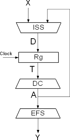
Figure 1 – Moore managing automaton base structure
Under the unitary encoding of Moore managing automaton states decoder doesn’t required, which in turn allows to the excitation functions system simplification of the register Rg.
In each CLB includes D-trigger, which allows the most optimal implement schemas with tree structure and a large number of states on FPGA, in particular, Petri nets. Moore automaton with unitary coding states can be represented as Petri net, which would exclude the traditional automaton synthesis.
Petri net model is a principal asynchronous and to display and analyze cause-effect relationships in the system. Events to bind to a particular time of any conversion are used.
A simple Petri net is a set N=(S,T,M,P,F), where:
- S = {s1, …, sN} – locations set;
- T = {t1, …, tN} – transitions set, such that S ∩ T = 0;
- M = {m1, …, mN} – labels set;
- P = {p1, …, pN} – events set;
-
F ⊆ μS×T×μS – incidence relation such that
а) ∀(S'1, t1, S"1), (S'2, t2, S"2) ∈ F : (S'1, t1, S"1) ≠ (S'2, t2, S"2) ⇒ t1 ≠ t2;б) {t| <S', t, S"> ∈ F} = T.
The conditions in paragraph 5 say, that for each transition t ∈ T exist only one element <S', t, S"> ∈ F, that specify for it the input locations set S' and output set S".
Petri net has a clear presentation in graph view, which includes four basic elements: positions (locations), transitions, arcs and labels. There is an example of such graph on fig. 2, setting a simple Petri net with three locations, three labels and two conversions.
This network operation is to move the labels m1-m3 through arcs between locations S1-S3 and the events shaping. Transitions t1-t2 define the labels movement conditions from locations S1 and S3. The original labels placement on the locations is the initial condition and can be arbitrary [2].
On this basis an arbitrary flip flow for the managing automaton is a particular case of Petri net with a single label, which corresponds to the current automaton state. Locations set S correspond to the automaton states set, the transitions set t – the conditional nodes set, the events set – the control signals collections set.
Thus, random managing automaton can be presented in the form of Petri net. In the case when the events occur in the presence of labels in a certain location, the net displays the behavior of Moore managing automaton. If events are formed during the labels movement between locations, depending on the transitions, the net displays the behavior of the Mealy automaton.
This scheme is implemented on the FPGA by one of the known methods.
The advantages of such managing automaton implementation on FPGA are:
- Identity blocks and structure automaton regularity.
- Minimal combination part, distributed throughout the FPGA schema.
- A small inputs number of combinational circuits, independent of the automaton states number.
- High speed automaton.
- The traditional synthesis lack.
For disadvantage of a method include the fact that the automaton states number cannot exceed the triggers number defined FPGA chip, which often corresponds to the CLB number.
Second chapter.
It is assumed to apply the Moore managing automaton states unitary coding in the Petri net form, which would exclude the automaton traditional synthesis by transition table. This will result in logical schema automaton minimizing to improve its performance. Also, such synthesis would allow the parallel control implementation.
Let us consider the Moore managing automaton implementation as Petri net given in fig. 3. Note that the algorithm branches a3 -> a4 and a6 -> a7 are parallel executed.
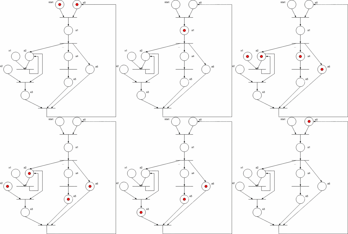
To implement this automaton schema on FPGA components it is needed to replace Petri net components in fig. 4 into their functional analogs: an automaton state position – by D-trigger, transition – by AND element, entrances set to the position combines by OR elements, arcs which connect locations and transitions are correspond the usual electrical connections. Fig. 5 shows the functional managing automaton schema received for flip flow by Petri net.
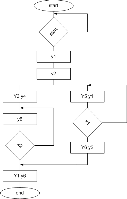
Figure 3 – Base flow graph
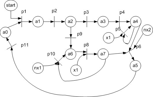
Figure 4 – Petri net for base flow graph
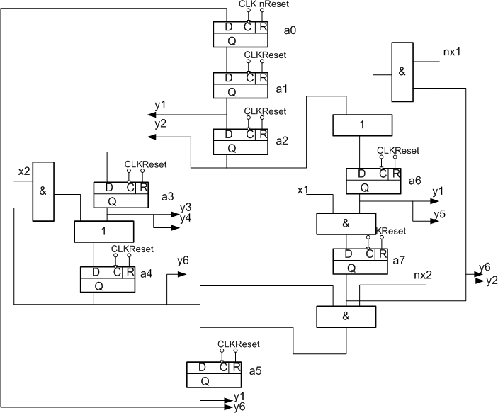
Figure 5 – Moore managing automaton functional schema based on flow graph
The schema works like that. At a signal Reset = "1" all the triggers, except for zero, are resetted to "0", and trigger a0 at this is setted to 1, which corresponds to the initial state, since at this it doesn’t produce any control signals (this is the start signal). In each cycle CLK in one or more (if in parallel branches) triggers is written "1", which corresponds to the transition from one state to another. At this the trigger, from which comes "1" writing, is written "0". To ensure the correct schema operation a reset signal must have duration of not more than one cycle, and worked out once during managing automaton startup.
Third chapter. The method of Moore managing automaton process synthesis is supposed. Software, realized automatic schema automaton designing on VHDL language is developed.
Fourth chapter. The method of Moore parallel managing automaton on FPGA performance evaluation is supposed. Moore managing automaton efficient area using by supposed structure is defined.
Important remark. During author's abstract writing master work is still not completed. Final completion: December, 2009. Work's full-text and materials on theme can be get from author or her supervisor after mentioned date.
Literature
- Грушвицкий Р.И. Проектирование систем на микросхемах программируемой логики / Р.И. Грушвицкий, А.Х. Мурсаев, Е.П. Угрюмов – СПб., БХВ-Петербург, 2002. – 608с.
- Баркалов А.А. Синтез автомата Мура на FPGA с унитарным кодированием состояний / А.А. Баркалов, А.А. Красичков, Халед Баракат.
- Захаров Н. Г. Синтез цифровых автоматов: Учебное пособие / Н.Г. Захаров, В.Н. Рогов – Ульяновск: УлГТУ, 2003 – 544с.
- Котов В. Е. Сети Петри. – М.: Наука, 1984 – 263с.
- Лазарев В.Г. Синтез управляющих автоматов / В.Г. Лазарев, Е.И. Пийль – М., Энергоатомиздат, 1989 – 328с.
- Питерсон Дж. Теория сетей Петри и моделирование систем. – М.: Мир, 1984 – 368с.
- Учебное пособие "Синтез цифровых автоматов" - http://venec.ulstu.ru/lib/2003/5_Zaharov_Rogov.pdf
- Структурные модели конечных автоматов при их реализации на ПЛИС - http://www.chipinfo.ru/literature/chipnews/200209/1.html
- Теория сетей Петри - http://ru.wikipedia.org/wiki/Сети_Петри
- Немченко А.В. - Параллельные цифровые автоматы - http://www.softcraft.ru/auto/etc/avn/avn1.shtml