Author's abstract
Statement of a task
Welding - the technological process widely applied in all branches for manufacturing new and repair of
maintained mechanisms, designs and the equipment.
In last years quickly develops automation of arc welding (welding by fusion) with application of industrial robots
which can be applied in all branches at manufacturing metalware. Welding by fusion it is possible to
connect practically all used for manufacturing designs metals and alloys of any thickness. This process is very
harmful to the person, is connected with strong noise, greater temperatures, influence of a smoke and intensive
light (sparking), automation provides high quality of seams, greater stability and speed of work.
The robots applied to automation of arc welding, represent universal reprogrammable manipulators. The control
system welding should provide with the robot fast adjustment of parameters of management for the set trajectory
of movement welding torches which can be set analytically by function of moving of a torch in time or is set by
the operator set of points which can be received experimentally. During welding the operator should have an
opportunity to correct a trajectory to provide accuracy of positioning no more necessary - ±0.1mm. Also it is
necessary to consider types of materials of welded products and their thickness on which speed of moving of a
head welding torches will depend. If speed of a torch will differ from set high quality of seams will not be
provided, even at a zero mistake of positioning. Since Smaller speed will not fuse edge of welded materials
enough, and greater - on the contrary will melt them.
The basic problem of management of arc welding is the problem of exact positioning, i.e. exact tracking of the
set trajectory in space and in time, at continuous planimetric management for performance concerning complex
handling problems. The major factors generating this problem, essential nonlinearity of dynamic and kinematic
model, dynamic interrelation between separate systems, and also not planned factors is: change of the program of
a trajectory or unexpected change of useful loading.
The majority before applied methods of management or did not consider change of dynamics in time, or were so complex
and bulky in the computing attitude that demanded very much a plenty of calculations on each step for a short time
interval. In the first case the set requirements to dynamic regulation were not provided, and in the second - led to
necessity of use of very powerful and dear controllers.
To elimination of problems nonlinearity the differential equations it is applied linearization dynamic model. Linearization
by means of classical methods with use of decomposition of the nonlinear differential equations in Taylor's number in a
vicinity of a working point requires recustomizing parameters of management at change of a working point.
Whether it is possible to apply a new general method of indemnification of interrelations to elimination of the same problems
and linearization the differential equations of dynamics with use diffeometrical transformations and theories of algebra. The
given approach is based on idea of reception "external linearization" complex nonlinear system with use diffeometrical
transformations of coordinates and a nonlinear feedback on a condition. This method allows to provide a block outcome of an
output; constructive algorithm of a finding of a nonlinear feedback for subsystems in which the number of outputs can be less
or to equally number of inputs; an outcome of outputs a nonlinear feedback from the point of view of a condition of system;
for maintenance of stability of a control system the nonlinear feedback incorporates to the controller of optimum correction
of mistakes.
Advantage of this method is that parameters of management do not require a feather to adjustment as linearization it is spent
not in a concrete point, and on the whole subset of nonlinear planes.
Up
1. THE ANALYSIS OF EXISTING ALGORITHMS OF MANAGEMENT OF HANDLING INDUSTRIAL ROBOTS.
1.1. The analysis of existing methods of synthesis of algorithms of management of the handling industrial robot.
Planning of a trajectory of movement of the manipulator of the industrial robot is carried out by means of algorithms of
management by planning. These algorithms of management are considered as nonlinear algorithms of division command movement
on degrees of mobility of the manipulator. Their realization is connected with the decision of the nonlinear equations
describing a configuration of the mechanism at set position of working bodies of industrial robots. For the decision of
such nonlinear problems resort or to the help of the COMPUTER, or imitating to modelling with use of real models of
handling systems.
For linearization the equations describing behaviour of handling system at small changes of coordinates of elements of the
mechanism, it is usual resort to differentiation on time of coordinates of position of parts in compound mechanism
connected by nonlinear dependences or to indemnification nonlinearity and interaction by means of regulators and a feedback.
Problem of management is development of algorithm demanded functioning drives of the manipulator. Thus some methods of
management are used by planning of a trajectory of movement of the manipulator of the industrial robot.
The method of management on a vector of speed consists in the task speed movements of working bodies of handling
system in the form of six-dimensional vector representing to a projection of vectors of angular speed of the worker organ
and speeds of its some point in any system of coordinates which are provided by algorithms of management so that completely
to define speed of working body in a current point of a trajectory.
Direct use of this decision for the purposes of management are limited to occurrence during management вырожденных configurations
of the mechanism which should be considered by algorithm of management. Such method of management is effective if necessary fast
translation of working body from one position in another, not demanding high accuracy of positioning. Besides the method possesses
sufficient complexity of realization.
The method of consecutive updatings of position is most widely applied in digital control systems. In this case the
algorithm of management on a vector of speed is formed as an increment of coordinates of the manipulator for one cycle
of calculation of algorithm.
Lack of a method is frequent sample of central points of a complex trajectory that transitions from one point to another
at planning a trajectory of movement did not change essentially necessary picture of movement.
The approached methods. At synthesis of a control system by the manipulator use the approached decisions which follow
from limitation of the task of values of coordinates. Usually take on three values: two extreme and one average, and for them
calculate the return Jacobian matrix, depending from a configuration of the manipulator, for all other values of coordinates
(including central, characteristic points of a trajectory) the return matrix is calculated interpolation. In many cases,
especially at presence of a feedback by position, it it appears quite enough at achievement of a ultimate goal of management.
Lack of a method are the mistakes arising at interpolation reaching great value, especially at absence of a feedback by position.
Method of management on a vector of force. On a vector of speed it is necessary to carry impossibility to lacks of a method
of management to provide formalization of aspiration of moving of working bodies of industrial robots in the set direction if on
the set trajectory there are points in which the matrix of a configuration of the manipulator is singular.
The tendency to simplification of managerial process and the calculations caused by it have led to use of a method of management
on a vector of force in which imitating the idea of management in the set direction is realized. Actually no forces are applied
on the manipulator, but watching drives develop such set of the generalized forces which are dynamically equivalent to the set
forces simulating their appendix to the manipulator. The calculator, having received on an input setting signals, defines the
generalized forces carried to coordinates, directly operated by a drive. In turn, drives constantly develop such generalized
forces which turn out on an output of the calculator. Amendments can automatically be entered into these generalized forces by
regulators and equalisers.
1.2. The analysis of existing methods of indemnification нелинейностей and outcomes of interactions in handling industrial
robots.
The primary goal of management of industrial robots is generating the external moments u(t) so that movement of the robot was
carried out on the chosen trajectory. Movement of the robot is usually carried out by two various controllable phases. First of
them is checking the phase of rough movement during which the robot moves from a primary position to a vicinity of the location
of the set purpose of lengthways preliminary certain trajectory. The second control phase is the stage of exact movement, when
working body of the robot dynamically communicate with object, using thus an information channel of a feedback from external
gauges for performance of a problem.
In case in robots the traditional watching technics nonlinearity and the interactions which are present at dynamics of the
manipulator, cannot be compensated at a stage of rough movement is used. With increase demands to performance data of
industrial robots becomes necessary acceptances in attention of the listed dynamic effects. During last time the big number
of improvements in schemes and algorithms of the direct control of industrial robots was offered to it.
Some researchers it was offered to use linearized models of systems as a basis for the further realization of an outcome
of regulation. Caen and the Mouth have developed the approached model of the optimum controller which led to suboptimum
regulation. Suboptimum regulation resulted from the approached replacement of nonlinear system linear and the subsequent
analytical finding of optimum control for linear system. Also the method of linear regulation on many variables has been
offered. However, based on linearized models the system of regulation can appear practically unacceptable if real operating
conditions will start to differ from the conditions incorporated at linearization. It can lead to not desirable deviations
of reaction of the robot from the set trajectory as it has been shown Frundom at modelling various methods of regulation.
One of the first methods in whom the robot is considered as the nonlinear, interconnected system with many inputs and many
outputs, was a technique of calculations of the rotating moments, investigated by the Floor, Markevich. This method is based
on use negative by return and positive return communications. The positive feedback is used for indemnification of forces of
the interaction arising between joints, and by means of a negative feedback calculation of the necessary correcting rotary
moments is made for indemnification of any deviations from the set trajectory. Thus it is necessary, that probably exact
calculation of inertial forces of reaction, force Кориолиса and centripetal force, and also gravitational forces. Thus,
operational characteristics of the given system of regulation substantially depend on accuracy of used model. The method of
definition of the rotating moments demands a significant amount of calculations that is often considered as its lack.
Regulation of speed of the designed movement represents a technique of definition of variable speeds of movement of the joint,
necessary for maintenance of moving of a trailer point of the robot in the set direction. At such scheme of management all the
established trajectories are set in cartesian coordinates. It is the certain advantage as the majority of users, possibly, with
greater ease can set sequence of moving in cartesian coordinates, than in variable coordinates of a site of connection. Ways of
calculation of the rotating moments and regulations of speed of the designed movement are combined in a method of regulation of
acceleration of the designed movement. In THIS method it is supposed, that demanded sites, speeds and accelerations of the set
movement of a hand are defined by the user. The listed methods also possess lacks: They demand presence itemized dynamic
model and long machine time for realization of calculations.
The basic advantage of various methods of adaptive regulation is absence of necessity of use of model of dynamics of the robot.
In reference model of the adaptive control the model corresponding by the standard gets out, and the algorithm of adaptation
modifies factors of strengthening in channels of a feedback of controllers. The algorithm of adaptation is set by a difference
between target signals of reference model and actual target perimeters of the robot. Management of the robot is carried out by
regulation of factors of strengthening in channels of a feedback for a site and speed so that its characteristics of the closed
contour were close to reference model. Lack of a method is laboriousness and multidimensionality at realization.
New current in designing operating systems for industrial robots is use of the theory of systems with variable structure. In
systems with variable structure on a surface of switching the so-called sliding mode takes place. At work in a sliding mode the
system remains tolerant to changes of parameters and indignations. Creation of the management inducing the sliding mode, does not
demand exact modelling; there is sufficient only a nobility of a parity between parameters of model. However, this method possesses
one lack following from minimization of time of the decision: exact definition of the moments of inclusion of adjusting entrance
signals appears inconvenient.
Up
2. MATHEMATICAL MODEL OF THE INDUSTRIAL ROBOT OF TYPE PUMA-560 WITH THE MINIMAL CONFIGURATION
2.1. Mathematical model of kinematics of the industrial robot
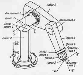 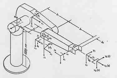
Fig. 2.1 - Manipulator PUMA-560.
The concept "with the minimal configuration" means the robot, that three first will be considered a part of the robot which
define position схвата the manipulator in space. In other words, last three steps of mobility which define orientation схвата
will not be considered.
For the considered robot according to matrixes of homogeneous transformations of coordinates for transition from i to (i-1)
system of coordinates are known:
For the handling robot of type PUMA-560, all which joints rotary, parameters di and di and
 are design data of joints. The parameter qi is a
variable. The concrete values of design data borrowed from, are resulted in tables 1 and 2. are design data of joints. The parameter qi is a
variable. The concrete values of design data borrowed from, are resulted in tables 1 and 2.
Table 1
Design data of robot PUMA-560
| a2,m |
a3,m |
a4,m |
a5,m |
| 0.432 |
0.019 |
0.125 |
0.432 |
Таблица 2
Weight-inertial characteristics of robot PUMA-560
| Part |
Weight |
The centers of weights |
Radiuses of inertia |
| i |
mi,kg |
xi,m |
yi,m |
zi,m |
kxi,m |
kyi,m |
kzi,m |
| 1 |
33.5 |
0 |
0 |
0.08 |
0.0451 |
0.0451 |
0.00579 |
| 2 |
73.3 |
-0.216 |
0 |
0.2175 |
0.05657 |
0.1847 |
0.1408 |
| 3 |
36.3 |
0 |
0 |
0.216 |
0.06728 |
0.06791 |
0.0036 |
| 4 |
8.95 |
0 |
0.02 |
0 |
0.00316 |
0.00211 |
0.00316 |
For reception of a homogeneous matrix  , Defining position схвата the manipulator
in space, it is necessary to execute (according to formalism Denavit-Hartenberg) operations of multiplication of matrixes , Defining position схвата the manipulator
in space, it is necessary to execute (according to formalism Denavit-Hartenberg) operations of multiplication of matrixes
 for i=1 for i=1 4: 4:
|

|
(2.5) |
In the given matrix us 4-th column, being a vector of position схвата the considered manipulator which coordinates look
like interests:
where

The received vector  Is nonlinear display of target coordinates of system which in
the further is used at linearization the equations of dynamics of the manipulator. Is nonlinear display of target coordinates of system which in
the further is used at linearization the equations of dynamics of the manipulator.
2. Mathematical model of dynamics of the industrial robot of type PUMA-560 in the form of equation Lagrang-Euler
Let's consider the robot with п in the kinematic pairs, not having superfluous degrees of mobility at which n - the measured
vector of the moments t(t) in kinematic pairs is connected with n - measured vector Q (t) corners of turn in hinges the
nonlinear dynamic equation of movement:
|

|
(2.9) |
where M(Q) - the symmetric positively certain matrix of inertia dimension n х n,
 - n - a measured vector-column of the moments caused by forces Кориолиса and
centrifugal forces: - n - a measured vector-column of the moments caused by forces Кориолиса and
centrifugal forces:
|

|
(2.10) |
|

|
(2.11) |
G(Q) - n - a measured vector of gravitational loading;
The equation (2.9) describes dynamics of the manipulator in the form of Euler-Lagrang. For reduction
of the nonlinear differential equations (2.9) to a special kind, we shall enter a designation:
|

|
(2.12) |
Then the equation (2.9) will become:
|

|
(2.13) |
The equation (2.13) in the further will be used at reception of the nonlinear equation of a special kind.
The problem of management of the manipulator consists in creation of such control system which provides tracking by a vector of
corners of turn in hinges Q (t) any set (basic) trajectory Qr(t), where Qr(t) - n - a measured vector-column
of any functions of time. It is expedient to admit, that these functions have derivatives of the first and second orders, i.e.
demanded angular speed  r(t) and angular acceleration r(t) and angular acceleration
 r(t) exist and are accessible directly, without necessity of operation of
differentiation Qr(t). It is desirable also that the control system of the manipulator provided tracking a trajectory
irrespective of weight of a cargo m i.e. that dynamic characteristics of the manipulator were tolerant to size of useful loading. r(t) exist and are accessible directly, without necessity of operation of
differentiation Qr(t). It is desirable also that the control system of the manipulator provided tracking a trajectory
irrespective of weight of a cargo m i.e. that dynamic characteristics of the manipulator were tolerant to size of useful loading.
Up
3. LINEARIZATION MATHEMATICAL MODEL OF DYNAMICS OF THE INDUSTRIAL ROBOT OF TYPE PUMA-560
3.1 Linearization mathematical model of dynamics of the robot on the basis of expansion in a Taylor series
We approximate nonlinear mathematical model of dynamic system (2.8) on a time interval ti<t<ti+Dt
by expansion in a Taylor series in a vicinity of a nominal operational (working) point linear invariant on time multivariate model
|

|
(3.1) |
where q(t) and T(t) - deviations of vectors of corners of turn and the moments in hinges from the rating values
t(ti) and Q(ti) in working point P={t(ti),Q(ti),Q(ti)}, that is
|
q(t)=Q(t)-Q(ti)
|
(3.2) |
|
T(t)=t(t)-t(ti)
|
(3.3) |
Three matrixes And, In, With dimension n х n, entering in линеаризованную model (3.1), depend on position of working point Р and
can be, are received from expressions:

and a matrix And always symmetric, positively certain and, hence, not вырожденная. The equation (3.1) represents system connected
linear, not dependent on time of the differential equations describing dynamics of the robot in increments at presence of
indignations in a vicinity of a nominal operational point.
Two variants of representation линеаризованной models of the robot (3.1) are possible, namely: model in space of a condition, i.e.
in time area, and model in the field of a complex variable, i.e. in frequency area.
For drawing up of model of the robot in space of conditions define elements of expressions  and
and  as variable conditions of system, and the equation (3.1) copy in a standard format: as variable conditions of system, and the equation (3.1) copy in a standard format:
|

|
(3.5) |
The order of this model is equal 2n, a vector of a condition  has dimension
2n has dimension
2n 1, all vectors are considered in time area. 1, all vectors are considered in time area.
Model of the robot in frequency area it is made by means of transformation Лапласа of the equations (3.1) therefore it is received:
|

|
(3.6) |
where T(s) and q(s) - n - measured vectors of an input and an output of system in frequency area.
3.2 Reduction of the equations of dynamics of the industrial robot of type PUMA-560 in the form of Lagrang-Euler to
a special kind
For reception of the nonlinear differential equation of a special kind we shall enter following designations for the
generalized coordinates:

the vector (x1,x2,…,x2n) is designated X, the vector (x1,x2,…,xn)
is designated  . The equation (2.9) can be presented in the standard form of a special kind
if to consider earlier the entered designations: . The equation (2.9) can be presented in the standard form of a special kind
if to consider earlier the entered designations:
|

|
(3.7) |
The maintenance of nonlinear functions f (x) and g (x) in the equation (3.7) becomes clear at its record in the form of components:
|

|
(3.8) |
Thus the векторно-matrix equation (3.8) on the basis of which it will be carried out linearization dynamic model of the manipulator
with application diffeometrial transformations of coordinates and a nonlinear feedback on a condition is received.
3.3 Linearization mathematical model of dynamics of the robot on the basis of diffeometrial transformations of coordinates and a
nonlinear feedback on a condition
For linearization dynamic model of the industrial robot of type PUMA-560 the nonlinear feedback of a kind is entered:
And diffeometrial transformation Т(х) such, that after realization of a nonlinear feedback and diffeometrial transformations
of coordinates the new (transformed) system is linear in Brunovsky to an initial form with the untied output.
Following designations appear in expression (3.9):
U(x) - a vector of the operating influences enclosed to the manipulator of the robot;
а(х) - a vector function;
b(х) - a nonspecial matrix;
V- a vector of entrance influences of system;
Нелинейная обратная связь может быть представлена в следующем виде:
|

|
(3.10) |
where
|

|
(3.11) |
|

|
(3.12) |
Jh - Jacobian matrix of function
Jh-1 - a matrix, invers Jacobian matrix;
DJh - a matrix, defined according to expressions:
|

|
(3.13) |
|
|
(3.14) |
Diffeometrial transformation of coordinates has a following appearance:
|

|
(3.15) |
where Lf- derivatives Lee;
|

|
(3.16) |
Private derivatives  and and  are Jacobian matrix;
With use resulted above a nonlinear feedback on a condition and диффеоморфного transformations the dynamic
model of the manipulator is represented in initial form Brunovsky with decomposition on target variables:
|

|
(3.17) |
|

|
(3.18) |
where z - a vector of a condition in the transformed system of coordinates of dimension (6x1);
А - a block-diagonal matrix of dimension (6x6), describing decomposition of conditions of parts
of the transformed model of the robot;
В - block-diagonal matrix of dimension (6x3), reflecting decomposition of operating influences
on parts of the transformed model of the robot;
С - block-diagonal matrix of dimension (3x6), defining decomposition of target coordinates of
hinges of the transformed model of the robot;
|

|
(3.19) |
The dynamic system described by the equations (3.17) and (3.18), consists of three independent subsystems of the following form:
|

|
(3.20) |
where

The given linear system with the untied output is shown schematically as block BCLS (Brunovsky initial linear system) on fig.3.1.
Fig.3.1 - Brunovsky initial linear system
Linearization, carried out by a nonlinear feedback, is "external linearization" unlike usual "internal linearization"
(decomposition in Taylor's number). Nonlinear character of initial system does not vary. Lineariz systems can be named
a nonlinear feedback "exact linearization" in sense of management. The exact general linearization systems and an outcome
of the output, carried out by a nonlinear feedback on a condition and diffeometrial transformation of coordinates, create
linear system. The received system is unstable as each linear subsystem has multiple zero poles. Hence, it is necessary to
lead stabilization of the received linear system.
As a result of lead linearization dynamic model of the robot by means of a nonlinear feedback on a condition and diffeometrial
transformations of coordinates, the mathematical model with decomposition of a condition on joints and with the untied output
of the manipulator is received linearization. On the basis of the received mathematical model it is possible to synthesize
algorithms of optimum control of the manipulator of the robot well developed linear methods.
Up
4. SYNTHESIS OF ALGORITHMS OF MANAGEMENT BY THE INDUSTRIAL ROBOT OF TYPE PUMA-560 OF THE MINIMAL CONFIGURATION
4.1. Synthesis of algorithms of a multivariate control system by the industrial robot - a multivariate regulator with the
combined management
The approach to synthesis of a control system by movement in the kinematic pairs, used in the present work, is based on the concept
so-called " return systems ". We shall consider linear, not dependent on time, multivariate installation (object of regulation)
цhere u фтв у - m-dimensional vectors - columns of an input and an output, a W (s) - its transfer function in the form of a matrix
dimension nхn. Return display (inversion) of this installation is the dynamic system, at which transfer function
When at consecutive connection the object of management (4.1) is preceded with its inversion (4.2) on which input the demanded
target signal yd (t) object moves, the inverse regulator will generate corresponding operating influence, providing on an output
of installation reproduction of a signal at (t) as by definition product of transfer function of object and its inversion is an
individual matrix of dimension mхm
The given concept can be used for management of nonlinear objects, in particular, with reference to robots. In case of small
deviations of parameters of object in a vicinity of working point Р nonlinear installation approximation quasilinear
invariant model on time W1(s) on a small time interval
ti<t<ti+ t. In this interval of time inversion
Qi(s) installations is used as a regulator of the direct channel of management for generating operating influence
uпк(t). Then factors of strengthening of a regulator of the direct channel of management "are updated" adjusted)
so that to compensate changes in time of factors линеаризованной to model Wi(s), the positions of a working
point of R.Kogda caused by changes the regulator of the direct channel of management is exact inversion of object of management,
a mistake of tracking e(t)=yd(t)-y(t), the representing difference between an input of a regulator (у) and an
output of system (yd) will be equal to zero. Hence, it is represented logical to consider a mistake of tracking
е(t) as a measure of a deviation of a regulator of the direct channel of management from exact inversion of object.
This information is used for adjustment of parameters of a regulator of the direct channel of management, and adjustment is
conducted so that the behaviour of a regulator was exact inversion of behaviour of object of management that provides qualitative
tracking the set trajectory yd(t). t. In this interval of time inversion
Qi(s) installations is used as a regulator of the direct channel of management for generating operating influence
uпк(t). Then factors of strengthening of a regulator of the direct channel of management "are updated" adjusted)
so that to compensate changes in time of factors линеаризованной to model Wi(s), the positions of a working
point of R.Kogda caused by changes the regulator of the direct channel of management is exact inversion of object of management,
a mistake of tracking e(t)=yd(t)-y(t), the representing difference between an input of a regulator (у) and an
output of system (yd) will be equal to zero. Hence, it is represented logical to consider a mistake of tracking
е(t) as a measure of a deviation of a regulator of the direct channel of management from exact inversion of object.
This information is used for adjustment of parameters of a regulator of the direct channel of management, and adjustment is
conducted so that the behaviour of a regulator was exact inversion of behaviour of object of management that provides qualitative
tracking the set trajectory yd(t).
Besides for increase of stability of the closed control system and improvement of quality of transients the regulator of a circuit
of feedback Ki(s) is used, generating for object of management operating signal Uoc(t) in R.Koeffitsienty's
working point of a circuit of a feedback also are constantly adjusted according to a mistake е(t) for indemnification of
changes Wi(s). Besides at realization of the law of management it is synthesized and the additional signal
uрт(t) is used, R.Etot corresponding a working point a signal helps to improve quality of management, providing
faster adaptation to changes of parameters of the unit, and increases flexibility of a control system. Proceeding from all aforesaid,
the general law of management is defined by expression:
|
u(t)=uпк(t)+uос(t)+uрт(t)
|
(4.4) |
The described technique of synthesis is illustrated by the block diagram on fig. 4.1
Fig. 4.1. - Structure of a control system
4.1.1. Synthesis of a regulator of the direct channel of management
Linearization model (5.4.3.1) of dynamics of the manipulator can be presented model in frequency area (through transfer function)
|

|
(4.5) |
Considering the above-stated, as transfer function Q(s) dimension n х n a regulator of the direct channel of management
inversion linearization models (4.5), i. е.
|

|
(4.6) |
The equation (4.6) gives simple expression of inversion линеаризованной to model (3.1) of the manipulator that provides an
opportunity of practical realization Q(s). It is necessary to note, that inversion Q(s) multivariate object of
regulation W(s) generally represents complex dynamic system. Then the law of management sold by a regulator of the
direct channel of management, is set by expression:
|

|
(4.7) |
or
|

|
(4.8) |
where  - a demanded n-dimensional vector-column of increments of corners of turn in hinges.
Realization of the law of management (4.8) with use of a regulator of the direct channel of the management representing inversion of
the robot, is carried out by direct submission in the direct channel of management of demanded signals of position - a demanded n-dimensional vector-column of increments of corners of turn in hinges.
Realization of the law of management (4.8) with use of a regulator of the direct channel of the management representing inversion of
the robot, is carried out by direct submission in the direct channel of management of demanded signals of position
 , speeds , speeds  and accelerations
  and their multiplication to matrixes C, B and A accordingly. and their multiplication to matrixes C, B and A accordingly.
4.1.2. Synthesis of a regulator of a feedback
For increase of stability of the closed control system by the manipulator and improvement of quality of transients the regulator of
a circuit of feedback K(s) is used:
where Kp and Kv - matrixes (dimension n х n) factors of a feedback by position and speed which are necessary
for defining. The law of management sold by a regulator of a circuit of a feedback, looks like:
|

|
(4.10) |
or
|

|
(4.11) |
where  - n-dimensional vector of increments of a mistake of tracking by position.
Actually the equation (4.11) represents the law of management of the channel of a feedback on a condition for linearization
models (3.1) of the robot as it contains signals of a feedback as on - n-dimensional vector of increments of a mistake of tracking by position.
Actually the equation (4.11) represents the law of management of the channel of a feedback on a condition for linearization
models (3.1) of the robot as it contains signals of a feedback as on  , and on , and on
 . Considering results of the above-stated analysis, we shall construct a control
system of movement in kinematic pairs " in increments ", having combined a regulator of a circuit of feedback K(s)
and a regulator of the direct channel of management Q(s) as shown in the block - the scheme fig. 4.2. . Considering results of the above-stated analysis, we shall construct a control
system of movement in kinematic pairs " in increments ", having combined a regulator of a circuit of feedback K(s)
and a regulator of the direct channel of management Q(s) as shown in the block - the scheme fig. 4.2.
Fig. 4.2. - the Control system of movement of the manipulator in increments
In view of fig. 4.2 law of movement in increments in frequency area is set as follows:
|

|
(4.12) |
Or in time area
|

|
(4.13) |
When the law of management in increments is applied by movement to nonlinear model of the manipulator,
the "full" law of management is set by expression:
|

|
(4.14) |
It is visible, that the "full" law of management represents the sum two component. First of them is value of a vector of
the moments in the kinematic pairs, enclosed in nominal working point Р, i. е.  .
The second a component is caused by regulators K(s) and .
The second a component is caused by regulators K(s) and  , Providing management
of movement in increments. Let further n - the measured "full" set vector is described by expression , Providing management
of movement in increments. Let further n - the measured "full" set vector is described by expression
 , yet the n-dimensional "full" vector of corners of turn is equal hinges , yet the n-dimensional "full" vector of corners of turn is equal hinges
 . Substitution of these expressions in the equation (4.14) gives the "full"
law of management certain through "total" variables: . Substitution of these expressions in the equation (4.14) gives the "full"
law of management certain through "total" variables:
|

|
(4.15) |
where  - n-dimensional "total" vector of a mistake of tracking. It is visible, that except
for two members corresponding regulators of a circuit of a feedback and the direct channel of management, at the full law of
management (4.15) there is a third member - n-dimensional "total" vector of a mistake of tracking. It is visible, that except
for two members corresponding regulators of a circuit of a feedback and the direct channel of management, at the full law of
management (4.15) there is a third member
|
|
(4.16) |
reflecting influence of position of a working point P.
4.2. Synthesis of algorithms of management by the industrial robot on the basis of diffeometrial transformations of coordinates
and a nonlinear feedback on a condition - diffeometrial a regulator
In the beginning the dynamic system new linear and opened on an output is stabilized. Then for maintenance of stability of the
stabilized system to неопределенностям in values of parameters of the robot and the task, the contour of optimum correction of
mistakes for each linear subsystem with the opened output is added.
4.2.1. Stabilization
Stabilization is carried out by use of a contour of linear feedback F in system and a desirable establishment of poles of
the closed system. As F is a constant блочно - a diagonal matrix, all system remains linear with the opened output, named
L&D - the block (fig. 4.3). For a new contour of a feedback are entered linear PD - regulators:
|

|
(4.17) |
where Fi=[fi1 fi2]. Then the system (3.20) becomes:
|
 , ,
|
(4.18) |
Poles each subsystem are defined by expression:
|
 , ,
|
(4.19) |
where  - factor of attenuation; - factor of attenuation;  - own frequency;
  . .
The desirable entrance signal for each subsystem can be received from the equations:
|
 , ,
|
(4.20) |
|
 , ,
|
(4.21) |
where  - a desirable trajectory. - a desirable trajectory.
4.2.2 Optimization of mistakes
For synthesis of an optimum control system it is necessary to consider mistakes
|
 , ,
|
(4.22) |
From the equations (4.18) - (4.22) it is possible to receive
|
 , ,
|
(4.23) |
i.e.

or
|
 , ,
|
(4.24) |
The contour of optimum correction of the mistakes is entered into a control system, providing minimization of criterion function
|
 , ,
|
(4.25) |
where R - the is positive-certain matrix; Q and S - positively-полуопределенные matrixes;
Т - time of the termination of process. According to the linear theory of optimum control optimum
correction is defined by expression:
|
 , ,
|
(4.26) |
where

is the is positive-certain matrix of the decision of equation Rikkatie

If to consider the established decision at  that that
 =0 and equation Rikkatie takes the form of the algebraic equation: =0 and equation Rikkatie takes the form of the algebraic equation:

From here (4.27) becomes:
|
 , ,
|
(4.27) |
or

where


The block diagram of a control system with optimum correction of mistakes is presented on fig. 4.3.
Fig. 4.3. - the Control system of the handling robot with диффеометрическим a regulator
Up
5. EXPERIMENTAL CHECK OF WORKING CAPACITY THE SYNTHESIZED ALGORITHMS OF MANAGEMENT ON PC
With the purpose of experimental check of working capacity of the synthesized algorithms of management modelling on IBM PC has
been lead. The program is developed for this purpose in MATLAB environment. Carrying out linearization a progressive method,
Whether based on application of the theory of groups manually is practically impossible. Object of modelling are the regulator
constructed with use of the classical theory of multivariate systems (a multivariate regulator) and the regulator synthesized
on the basis of the specified newest method of management. Modelling is lead in two modes: at absence (1 mode) and at presence
(2 mode) parametrical indignations.
Fig 5.1. - Example of work of the manipulator
The comparative estimation of experimental results of modelling of the equations of dynamics of the robot of the minimal
configuration with synthesized multivariate and diffeometrial regulators shows essential advantage of algorithms of the
management based on the newest method. So, at significant change of weight of loading for the newest method the mistake of
tracking of a trajectory has not exceeded 0.1 mm while the mistake of a multivariate regulator has exceeded 4 mm. At presence
in system of modelling mistakes (on 50 %) a multivariate regulator loses a deviation of parameters of model of object stability,
diffeometrial the regulator at modelling in similar conditions keeps stability and demanded accuracy of positioning (0.1 mm).
Up
6. DEVELOPMENT of ALGORITHMS of MANAGEMENT ON THE BASIS OF ROBUST SYSTEMS
Following development cycle of system is creation of system робастного managements, клторая is based on the modern formalized
approaches to mathematical modelling, research and the projected systems. By consideration of adaptive control systems we
aspired to the best management from the point of view of the set criterion of an optimality. Adaptive САУ, reacts during
functioning to change of properties ОУ both external influences and adapting to new conditions on the basis of change of
structure and parameters of management of devices so that the parameter of quality reached extreme value.
The main task of synthesis робастных control systems is search of the law of management which would keep target variable systems
and signals of a mistake in the set admissible limits despite of presence uncertainty in a contour of management. Uncertainty
can accept any forms, however the most essential are noise, nonlinearity, and discrepancy in knowledge of transfer function of
object of management. Therefore the further разроботка will be devote to development робастного a regulator ensuring the
functioning system in conditions of the set uncertainty.
Up
The list of the sours
- Шахнипур М. Курс робототехники: Пер. с англ.- М.: Мир, 1990. - 527с.
- Фу К., Гонсалес Р., Ли К. Робототехника: Пер. с англ. М.: Мир, 1989. - 621с.
- Броккет Р. У. Алгебры Ли и группы в теории управления. Математические методы в теории систем. М.: Мир, 1979.
- Андреев Ю. Н. Дифференциально-геометрические методы в теории управления. Автоматика и телемехника 1982г. вып. 10.
- Системы очувствления и адаптивные промышленные роботы / В.Б. Брагин, Ю.Г. Войлов, Ю.Д. Жабитинский и др.;
Под общ. ред. Е.П. Попова, В.В. Клюева. - М.: Машиностроение, 1988. - 392с.
- Изерман Р. Цифровые системы упрвления: Пер. с англ. - М:Мир, 1984. - 541с.
- Уткин В.И Скользящие режимы в задачах оптимизации и управления. М.: Наука, 1981г. -368с.
- Y. L. Chen, Nonlinear feedback and computer control of robot arm, Ph. D. dissertation, Dept of System Science and Math.,
Washington Univ., St Louis, MO, Dec., 1984.
- Дьяконов В. Simulink 4. Специальный справочник.-СПб:Питер, 2002. - 528с.:ил.
- Дьяконов В. Круглов В. Математические пакеты расширения MATLAB. Специальный справочник.-СПб:Питер, 2001. - 480с.:ил.
|